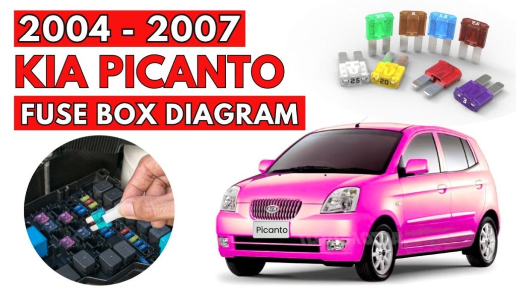
KIA Picanto (2004 – 2007) Fuse Box Diagrams & Location
The KIA Picanto (2004–2007) fuse box diagrams and location guide explain how to find and access fuse boxes. To maintain vehicle performance and safety, learn fuse layouts to troubleshoot electrical faults and fix them quickly.
Fuse Box Locations
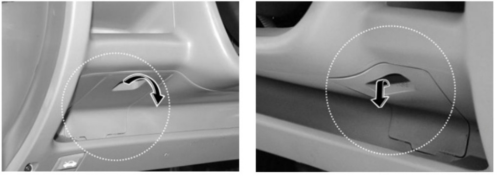
Instrument panel Fuse Box
The fuse box is located behind the cover below the steering wheel.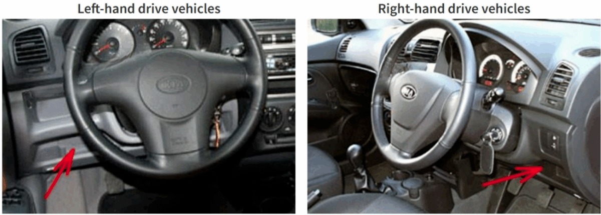
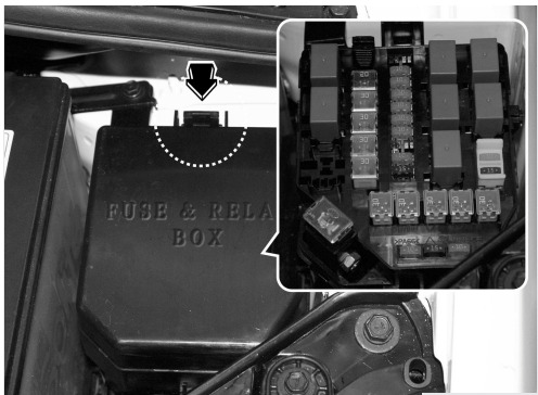
Engine Compartment Fuse Box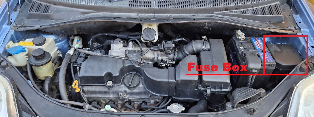
Instrument panel Fuse Box Diagram
KIA Picanto (2004 to 2007)
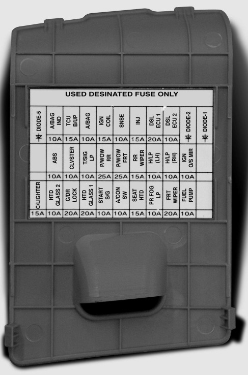
Assignment of the fuses in the Instrument panel
| Description | Amp rating | Protected component |
|---|---|---|
| START SIG | 10A | Start motor |
| RR FOG LP | 10A | Rear fog light |
| A/CON SW | 10A | Air conditioner |
| CLUSTER | 10A | Cluster |
| SEAT HTD | 15A | Seat warmer |
| C/LIGHTER | 15A | Cigar lighter |
| A/BAG | 10A | Airbag |
| R/WIPER | 15A | Rear wiper |
| ABS | 10A | Anti-lock brake system |
| IGN COIL | 15A | Ignition |
| T/SIG LP | 10A | Turn signal light |
| HTD GLASS1 | 20A | Rear window defroster |
| HTD GLASS2 | 10A | Rear window defroster |
| P/WDW RR | 25A | Power window (rear) |
| IGN O/S MIR | 10A | Outside rearview mirror |
| P/WDW FRT | 25A | Power window (front) |
| FRT WIPER | 20A | Front wiper |
| H/LP (LH) | 10A | Headlight (left) |
| H/LP (RH) | 10A | Headlight (right) |
| FUEL PUMP | 10A | Fuel pump |
| INJ | 15A | Injection |
| SNSR | 10A | O 2 Sensor |
| C/DR LOCK | 20A | Central door lock |
| A/BAG IND | 10A | Airbag warning |
| TCU B/UP | 15A | Automatic tranaxle |
| DSL ECU1 | 20A | – |
| DSL ECU2 | 10A | – |
Engine Compartment Fuse Box Diagram
KIA Picanto (2004 to 2007)
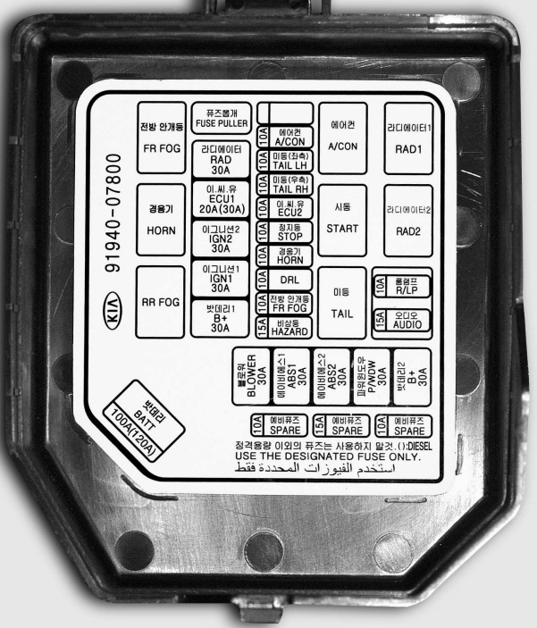
Assignment of the fuses in the Engine compartment
| Description | Amp rating | Protected component |
|---|---|---|
| ECU1 | 20A (30A) | Engine control unit |
| STOP | 10A | Stop light |
| FR/FOG | 10A | Front fog light |
| A/CON | 10A | Air conditioner |
| HORN | 10A | Horn |
| ECU2 | 10A | Engine control unit |
| SPARE | 10A | spare fuse |
| SPARE | 15A | spare fuse |
| SPARE | 10A | spare fuse |
| ABS2 | 30A | Anti-lock brake system |
| ABS1 | 30A | Anti-lock brake system |
| B+ | 30A | In panel B+ |
| BLOWER | 30A | Blower |
| IGN1 | 30A | Ignition |
| IGN2 | 30A | Ignition |
| TAIL LH | 10A | Tail light (left) |
| TAIL RH | 10A | Tail light (right) |
| DRL | 10A | Daytime running light |
| HAZARD | 15A | Hazard warning flasher |
| R/LP | 10A | Room lamp |
| AUDIO | 15A | Audio |
| P/WDW | 30A | Power window |
| RAD | 30A | Radiator fan |
| BATT | 100A (120A) | Alternator, Battery |
| F/FOG | – | Front fog light relay |
| A/CON | – | Air conditioner relay |
| HORN | – | Horn relay |
| START | – | Start motor relay |
| RAD1 | – | Radiator fan relay |
| RAD2 | – | Radiator fan relay |
| RR FOG | – | Rear fog light relay |
| TAIL | – | Tail light relay |
Diesel sub Fuse Box Diagram
KIA Picanto ( 2004 to 2007)
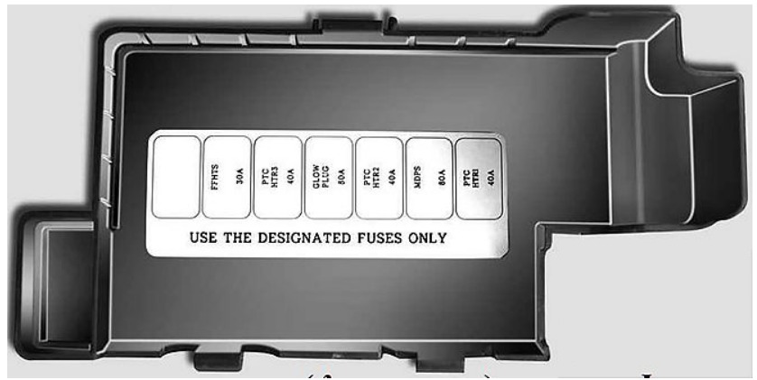
Assignment of the fuses in the Engine compartment (Diesel only sub fuse panel)
| Description | Amp rating | Protected component |
|---|---|---|
| FFHTS | 30A | Fuel filter heater temporary sensor |
| GLOW PLUG | 80A | Glow plug |
| MDPS | 80A | Motor driven power steering |
| PTC HTR1 | 40A | PTC heater 1 |
| PTC HTR2 | 40A | PTC heater2 |
| PTC HTR3 | 40A | PTC heater3 |