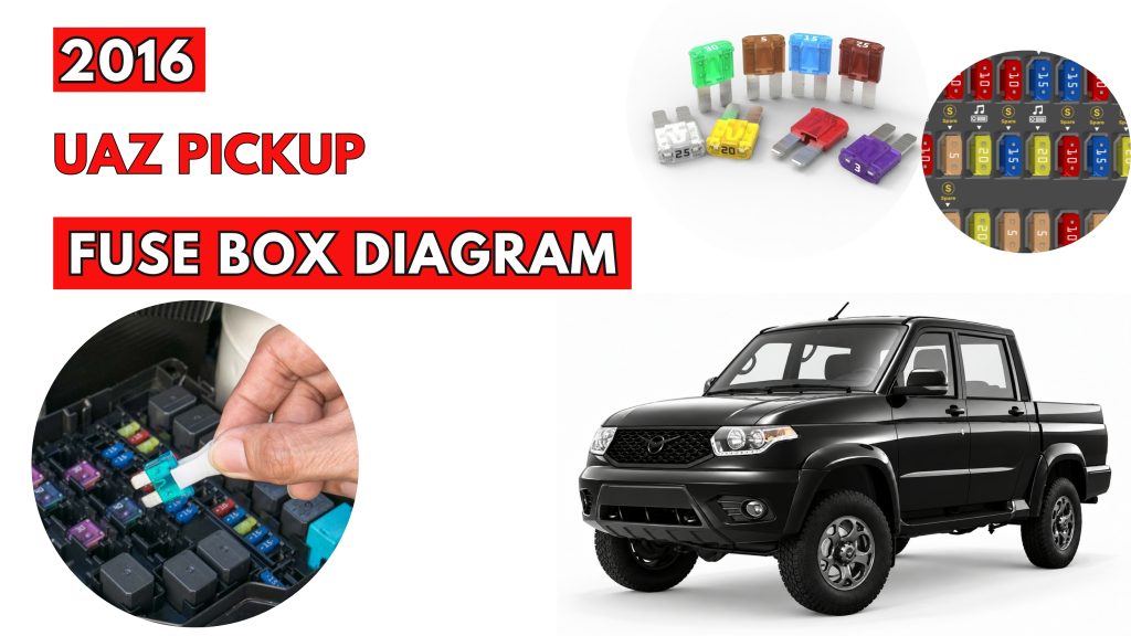
UAZ PICKUP 2016 Fuse Box Location & Diagrams
The UAZ Pickup (2016) uses fuses to protect important electrical circuits and components. Knowing the correct fuse locations and assignments helps with troubleshooting electrical problems. This guide covers fuse box locations, diagrams, fuse ratings, and protected components for the UAZ Pickup.
Fuse Box Location
Passenger Compartment Fuse Box
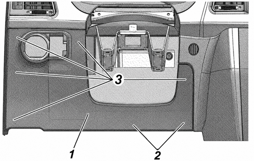
The cabin relay and fuse box is located under the cap on the instrument panel, left from the steering column. The scheme of relays and fuses is located on the inner side of the box cap.
Fuse Box cover
- relay/fuse box cover;
- cover latches
- cover clips.
Engine Compartment Fuse Box
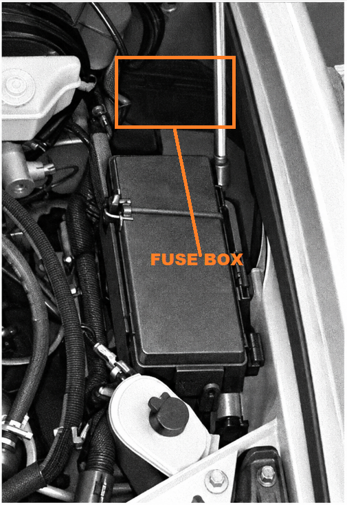
The relay and fuse box under the hood is located on the left, behind the battery.
Fuse Box Diagrams
Passenger Compartment Fuse Box
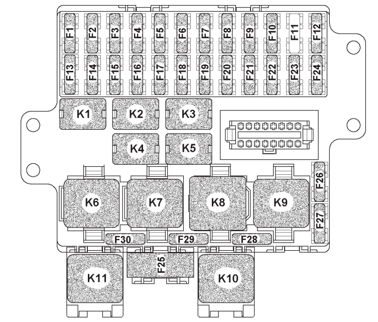
| Designation | Current (A) | Protected Circuits / Description |
|---|---|---|
| F1 | 10 | Dymos transfer case 15 A |
| F2 | 15 | Cabin socket |
| F3 | 10 | Air conditioner compressor |
| F4 | 30 | Power options relay box 30 A |
| F5 | 7.5 | Brake signal switch, interior lighting lamps, glove compartment lamp, luggage compartment lamp |
| F6 | 40 | Heating and air conditioning system, tailgate and mirror heating switch |
| F7 | 10 | Left fog light |
| F8 | 10 | Right fog light |
| F9 | 20 | Windshield wiper switch, windshield wiper, driver’s switch box, rear-seat passenger switch box, rear bodyshell heater |
| F10 | 20 | Heating of glass tailgate, mirrors, light control module |
| F11 | – | Not installed |
| F12 | 20 | Cigarette lighter, luggage compartment socket |
| F13 | 30 | Dymos transfer case 30 A |
| F14 | 10 | Window lifters (driver door module) |
| F15 | 5 | Cluster 34 A, reverse movement switch, speed sensor 1 A, alarm signal switch 2 A |
| F16 | 15 | Airbag |
| F17 | 10 | Multimedia system |
| F18 | 15 | Differential lock |
| F19 | 10 | Left high beam |
| F20 | 10 | Right high beam |
| F21 | 7.5 | Left low beam |
| F22 | 7.5 | Right low beam |
| F23 | 5 | Right parking lamp |
| F24 | 5 | Left parking lamp |
| F25 | 60 | Windshield heating |
| F26 | 10 | Reserve |
| F27 | 10 | Reserve |
| F28 | 30 | Reserve |
| F29 | 25 | Reserve |
| F30 | 20 | Reserve |
| K1 | – | Fog lamps switch relay |
| K2 | – | High beam switch relay |
| K3 | – | Additional interior heater relay |
| K4 | – | Low beam switch relay |
| K5 | – | Air conditioner compressor relay |
| K6 | – | Tailgate window and mirrors heater switch relay |
| K7 | – | Intermittent wiper relay |
| K8 | – | Additional (discharge) relay |
| K9 | – | Windshield heater relay |
| K10 | – | Windshield heater timer relay |
| K11 | – | Rear axle differential lock relay |
Engine Compartment Fuse Box
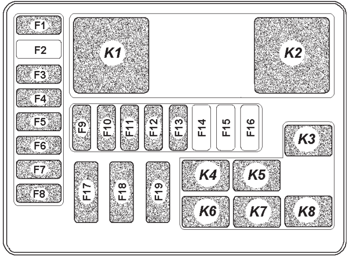
| Designation | Current (A) | Protected Circuits / Description |
|---|---|---|
| F1 | 15 | Horn |
| F2 | – | Not installed |
| F3 | 30 | Electric fan 2 |
| F4 | 25 | ABS (ESP) |
| F5 | 5 | Instrumentation |
| F6 | 20 | Oil pump |
| F7 | 20 | Starter motor |
| F8 | 30 | Electric fan 1 |
| F9 | 10 | Microprocessor-based Engine Control System (IMECS) |
| F10 | 10 | ABS (ESP) |
| F11 | 20 | Heater |
| F12 | 5 | Heater |
| F13 | 25 | Heater |
| F14 | – | Not installed |
| F15 | – | Not installed |
| F16 | – | Not installed |
| F17 | 60 | Mounting block |
| F18 | 40 | ABS (ESP) |
| F19 | 60 | Mounting block |
| K1 | – | Starter motor relay |
| K2 | – | Heater relay |
| K3 | – | Heater relay |
| K4 | – | Horn relay |
| K5 | – | IMECS relay |
| K6 | – | Electric fan relay |
| K7 | – | Oil pump relay |
| K8 | – | Electric fan relay |