Ram ProMaster City (2019-2022) Fuse Box Location and Diagrams
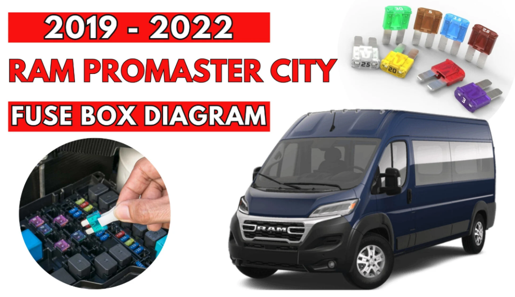
Finding the fuse box in a Ram ProMaster City is essential for troubleshooting issues like a dead radio, faulty power outlets, or lighting failures. For the 2019-2022 model years, the vehicle typically utilizes two primary fuse locations.
Fuses
WARNING!
- When replacing a blown fuse, always use an appropriate replacement fuse with the same amp rating as the original fuse. Never replace a fuse with another fuse of higher amp rating. Never replace a blown fuse with metal wires or any other material. Do not place a fuse inside a circuit breaker cavity or vice versa. Failure to use proper fuses may result in serious personal injury, fire and/or property damage.
- Before replacing a fuse, make sure that the ignition is off and that all the other services are switched off and/or disengaged.
- If the replaced fuse blows again, contact an authorized dealer.
- If a general protection fuse for safety systems (air bag system, braking system), power unit systems, (engine system, transmission system) steering system or Body Control Module (BCM) blows, contact an authorized dealer.
CAUTION!
If it is necessary to wash the engine compartment, take care not to directly hit the fuse box or the windshield wiper motors with water.
The fuses protect electrical systems against excessive current.
When a device does not work, you must check the fuse element inside the blade fuse for a break/melt.
Also, please be aware that using power outlets for extended periods of time with the engine off may result in vehicle battery discharge.
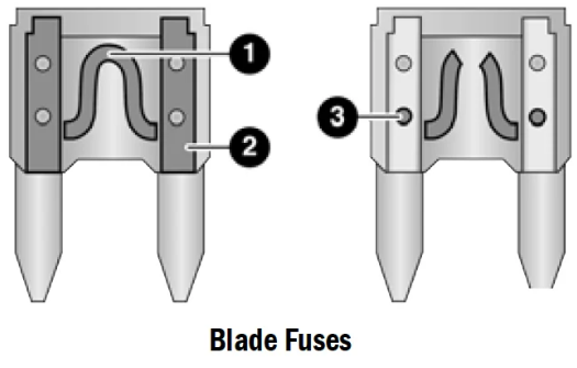
- Fuse Element
- Blade Fuse with a good/functional fuse element
- Blade fuse with a bad/not functional fuse element (blown fuse)
Underhood Fuses
The Front Distribution Unit is located on the right side of the engine compartment, next to the battery. To access the fuses, remove fasteners and remove the cover.
CAUTION!
When installing the power distribution center cover, it is important to ensure the cover is properly positioned and fully latched. Failure to do so may allow water to get into the power distribution center and possibly result in an electrical system failure.
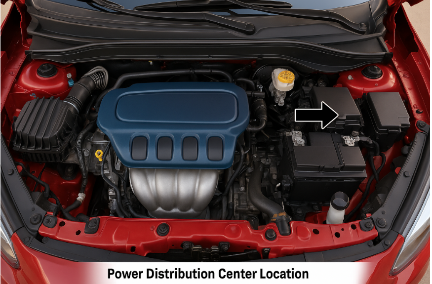
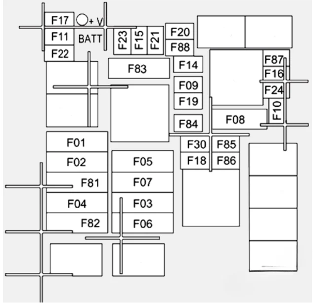
The ID number of the electrical component corresponding to each fuse can be found on the back of the cover.
| Cavity | Maxi Fuse | Mini Fuse | Description |
| * If Equipped | |||
| F01 | 60 Amp Blue | – | Body Controller |
| F02 | 40 Amp Orange | – | Rear Power Windows, Fog Lamps, Front Heated Seats * |
| Cavity | Maxi Fuse | Mini Fuse | Description |
| * If Equipped | |||
| F02 | 30 Amp Green | – | Rear Power Windows, Front Heated Seats Fog Lamps * |
| F02 | 20 Amp Yellow | – | Front Heated Seats * |
| F03 | 20 Amp Yellow | – | Ignition Switch |
| F04 | 40 Amp Orange | – | BSM System Module |
| F06 | 20 Amp Yellow | – | Radiator Fan – Low Speed |
| F07 | 50 Amp Red | – | Radiator Fan – High Speed |
| F08 | 40 Amp Orange | – | Blower Motor |
| F09 | – | – | – |
| F10 | – | 15 Amp Blue | Horn |
| F11 | – | 10 Amp Red | Secondary Loads ECM |
| F14 | – | 15 Amp Blue | High Beam |
| F15 | – | – | – |
| F16 | – | 5 Amp Tan | ECM and Transmission Shifter |
| F17 | – | 25 Amp Clear | ECM Power Loads |
| F18 | – | 5 Amp Tan | ECM Load, Main Relay |
| F19 | – | 7.5 Amp Brown | Air Conditioning |
| F20 | – | 30 Amp Green | Rear Defroster * |
| F21 | – | 5 Amp Tan | Key Unlock |
| F22 | – | 10 Amp Red | Primary ECM Loads |
| Cavity | Maxi Fuse | Mini Fuse | Description |
| * If Equipped | |||
| F23 | – | 20 Amp Yellow | BSM System |
| F24 | – | 5 Amp Tan | BSM System, Positive Key and Steering Angle Sensor |
| F30 | – | 15 Amp Blue | 2nd Instrument Panel Power Outlet (Battery) |
| F83 | 20 Amp Yellow | – | Fuel Pump |
| F84 | – | 15 Amp Blue | AT Module |
| F85 | – | 15 Amp Blue | Rear Power Outlet 12 Volts (ACC/ON/ RUN) |
| F86 | – | 15 Amp Blue | IP Power Outlet 12 Volts (ACC/ON/ RUN) |
| F87 | – | 5 Amp Tan | IBS |
| F88 | – | 7.5 Amp Brown | External Mirror Defrost * |
Interior Fuses
The interior fuse panel is part of the Body Control Module (BCM) and is located on the driver’s side under the instrument panel.
NOTE:
Please contact an authorized dealer for BCM fuse replacement.
Fuse Box Location
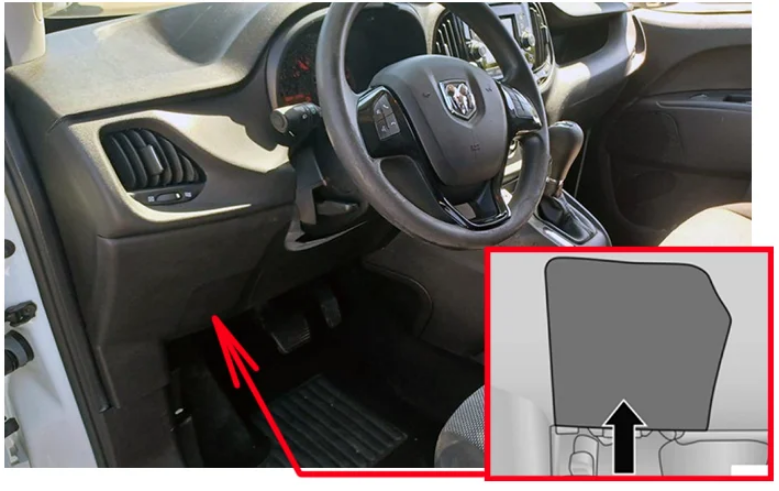
Fuse Panel Cavity Locations
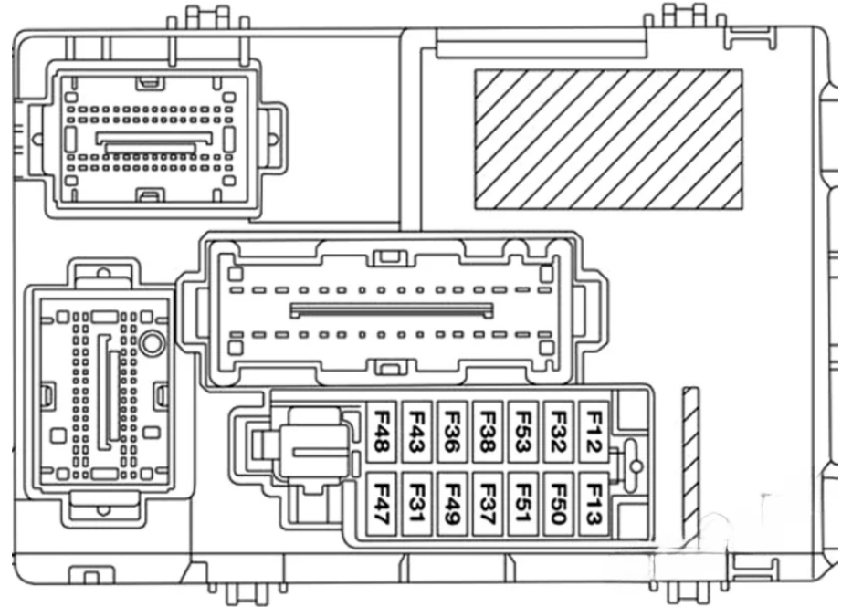
| Cavity | Mini Fuse | Description |
| F53 | 5 Amp Beige | KL 30 (+30) – IPC, FTM |
| F38 | 20 Amp Yellow | Central Doors Locking |
| F36 | 15 Amp Blue | KL 30 (+30) – TPMS, EOBD, HVAC, Radio, USB, SGW |
| F43 | 15 Amp Blue | Bi-Directional Washer Pump |
| F48 | 20 Amp Yellow | Passenger Power Windows |
| F13 | 7.5 Amp Brown | Supply for left low beam bulb or discharge lamp |
| F50 | 7.5 Amp Brown | KL 15 (+15) – Air-Bag |
| F51 | 7.5 Amp Brown | KL 15 (+15) – External Mirror Adjustment Command, HVAC, RVC, HWB Coils |
| F37 | 5 Amp Beige | KL 15 (+15) – Brake Pedal Switch (N.O.), IPC, Brake Pedal Switch (N.C.) |
| F49 | 5 Amp Beige | KL 15 (+15) – PAM, CSS Lighting, TTM, SGW, Heaters Light, ECM Backlighting |
| F31 | 5 Amp Beige | KL 15a (INT A) – HWB, MCO |
| F47 | 20 Amp Yellow | Driver Power Windows |
Central Unit Fuse Panel — If Equipped
The central power fuse panel is located on the driver’s side under the instrument panel.
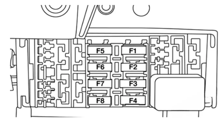
| Cavity | Mini Fuse | Description |
| * If Equipped | ||
| F1 | 10 Amp Red | Front Heated Seat Passenger * |
| F2 | 10 Amp Red | Front Heated Seat Driver * |
| F3 | 20 Amp Yellow | Rear Power Window Driver side * |
| F4 | 20 Amp Yellow | Rear Power Window Passenger side * |
| F5 | 15 Amp Blue | Fog Lamps * |