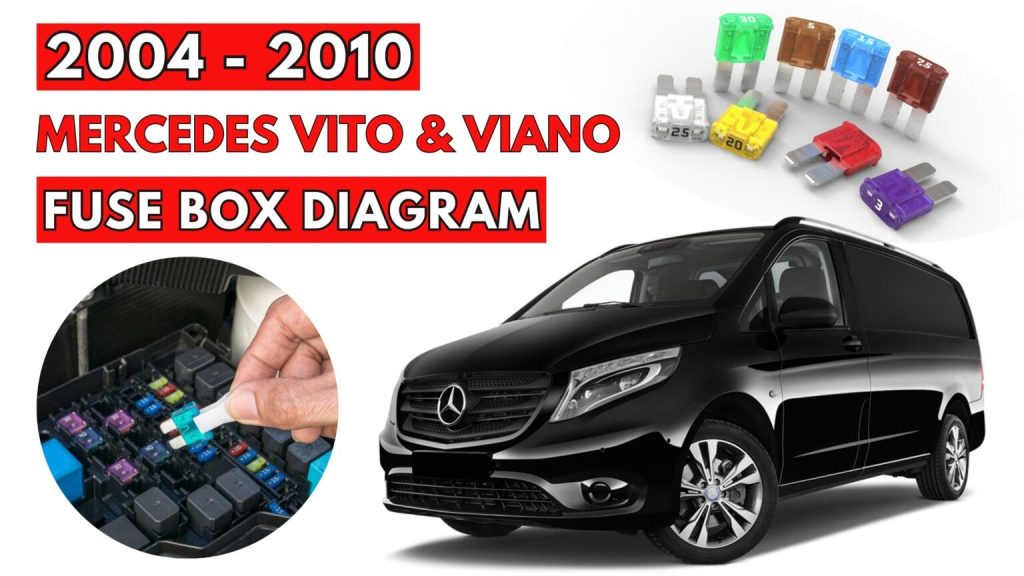
Mercedes (Vito & Viano) 2004 – 2010 Fuse Box Diagrams & Location
This guide includes diagrams and locations for the fuse boxes in Mercedes Vito and Viano from 2004 to 2010. This article can help you discover and understand fuses for more effective electrical troubleshooting and maintenance.
Fuses
The electrical fuses in your vehicle serve to switch off malfunctioning power circuits. If a fuse is blown, the components and systems secured by that fuse will stop operating. A blown fuse must be replaced by an appropriate spare fuse (recognizable by its color or the fuse rating given on the fuse) of the amperage recommended in the fuse chart.
Before replacing fuses
- Engage the parking brake.
- Make sure the automatic transmission is in park position P.
The transmission position indicator in the multifunction display should be on P. - Switch off all electrical consumers. X Turn off the engine.
- Remove the SmartKey from the starter switch.
- Vehicles with KEYLESS-GO: Open the driver’s door (this puts the starter switch in position 0, same as with the SmartKey removed from the starter switch). The driver’s door then can be closed again.
Fuse box Locations
2004 – 2010 Mercedes (Vito & Viano)
Main Fuse Box
The fuse box is located in the engine compartment on the passenger’s side.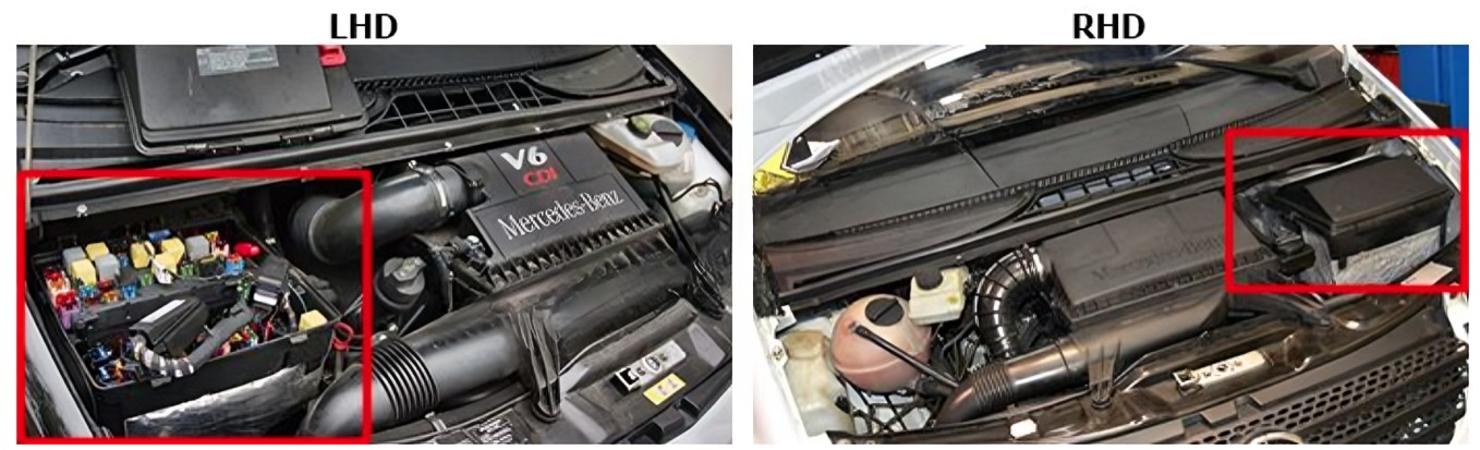
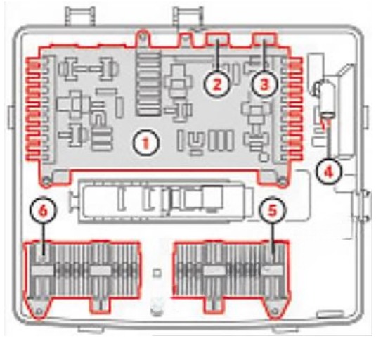
- Main fuse holder
- Fuse box F4
- Fuse box F5
- Main fuse F1
- Fuse block F34
- Fuse block F35
Fuse box under the driver’s seat
Main Fuse Box Diagram
2004 – 2010 Mercedes (Vito & Viano)

Assignment of the fuses in the Main Fuse Box
| No | Consumer | Amp |
|---|---|---|
| 1 | Windscreen wipers | 30 |
| 2 | Horn | 15 |
| 3 | Brake lamp switch | 5 |
| 4 | Heating | 7.5 |
| 5 | Diagnostics socket, rotary light switch, instrument cluster | 5 |
| 6 | Engine components | 5 |
| 7 | Rear wiper | 30 |
| 8 | Terminal 87 (1) | 10 |
| 9 | Terminal 87 (2) | 15 |
| 10 | Terminal 87 (3) | 10 |
| 11 | Terminal 30 Z engine | 7.5 |
| 12 | Rear window heating | 30 |
| 13 | Ignition lock/instrument panel | 7.5 |
| 14 | Brake system | 7.5 |
| 15 | Headlamp range control | 5 |
| 16 | Starter motor | 25 |
| 17 | Fuel pump | 15 |
| 18 | Cigarette lighter/glove compartment lighting | 15 |
| 19 | Radio | 5 |
| 20 | M112 ignition coils | 15 |
| 20 | Diesel HFM | 5 |
| 21 | Automatic transmission gearshift | 7.5 |
| 22 | Tachograph | 7.5 |
| 23 | Airbag control unit | 10 |
| 24 | Japanese rear-view mirror | 5 |
| 25 | Trailer control unit | 5 |
| 26 | Cut-off relay | 5 |
| 27 | Terminal 15 body/ equipment manufacturer | 5 |
| 28 | Transmission control unit | 10 |
| 29 | Start-off assist system | 5 |
| 30 | Unassigned | – |
| 31 | ATA horn | 10 |
| 32 | Mobile phone/VICS socket | 5 |
| 33 | Airbag, automatic child seat recognition | 10 |
| 34 | Terminal 15 R body/ equipment manufacturer | 5 |
| 35 | Overhead control panel | 7.5 |
| 36 | Lumbar adjustment (seat) | 10 |
| 37 | Make-up mirror light | 7.5 |
| 38 | Rear-compartment entertainment | 7.5 |
| 39 | Unassigned | – |
| 40 | Engine fuse (diesel) | 10 |
| 40 | Engine fuse (petrol) | 20 |
| 41 | Engine fuse (diesel) | 10 |
| 41 | Engine fuse (petrol) | 20 |
| F1 | Terminal 30 electricalsystem, alternator | 225 A |
| F4 | Air-conditioning fan (incooling unit) | 60 A |
| F5 | Secondary air pump | 40 A |
Fuse Block F34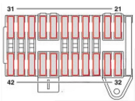
| No | Consumer | Amp |
|---|---|---|
| 21 | Light switch and upper section of control panel | 5 |
| 22 | Rear-compartment entertainment | 7.5 |
| 23 | Interior light | 10 |
| 24 | Overhead control panel and sliding/tilting sunroof | 7.5/25 |
| 25 | Rear-compartment sliding/tilting roof | 25 |
| 26 | Auxiliary heating, radio receiver | 5 |
| 27 | Front-compartment air conditioning | 7.5 |
| 28 | Socket for rear-compartment entertainment | 15 |
| 29 | Mobile phone/CD changer/microphone control module | 7.5 |
| 30 | Seat heating controls | 30 |
| 31 | Tachograph | 5 |
| 32 | Diagnostics gateway | 5 |
| 33 | Diagnostics socket | 10 |
| 34 | Audio gateway | 15 |
| 35 | Unassigned | – |
| 36 | Headlamp cleaning system | 30 |
| 37 | ATA battery horn | 10 |
| 38 | Steering column lock | 20 |
| 39 | Front-compartment blower | 40 |
| 40 | ABS control unit | 25 |
| 41 | ABS control unit | 40 |
| 42 | Radio/COMAND | 15 |
Fuse block F35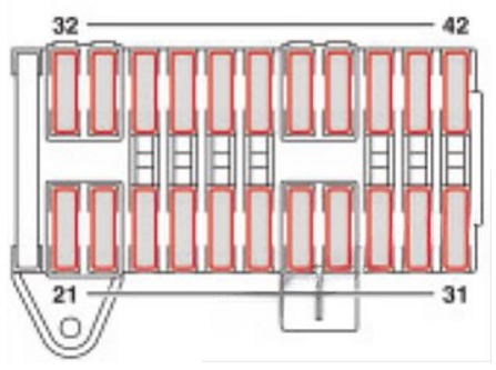
| № | Consumer | Rating |
|---|---|---|
| 21 | 12-volt socket for passenger compartment, left | 15 A |
| 22 | 12-volt socket for passenger compartment, right | 15 A |
| 23 | Trailer power socket | 20 A |
| 24 | Trailer recognition unit | 25 A |
| 25 | Driver’s seat adjustment | 30 A |
| 26 | Co-driver’s seat adjustment | 30 A |
| 27 | Electric sliding door, left | 30 A |
| 28 | Electric sliding door, right | 30 A |
| 29 | Rear-compartment blower | 30 A |
| 30 | Air suspension system | 40 A |
| 31 | Parktronic | 10 A |
| 32 | Tyre pressure monitor | 5 A |
| 33 | Sound system | 25 A |
| 34 | Mobile phone control unit/VICS, TV booster | 5 A |
| 35 | Auxiliary heating control unit | 20 A |
| 36 | Unassigned | – |
| 37 | Rear-compartment air-conditioning system | 5 A |
| 38 | COMAND camera control | 7.5 A |
| 39 | Conventional taximeter | 5 A |
| 40 | 12-volt socket, rear right | 15 A |
| 41 | Roof indicator light control unit | 10 A |
| 42 | Unassigned | – |
Fuse Box under the driver’s seat –Diagram
2004 – 2010 Mercedes (Vito & Viano)
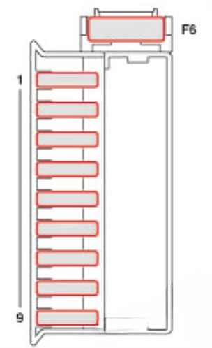
| No | Consumer | Amp |
|---|---|---|
| F6 | SAM-SRB | 80 |
| 1 | Door control unit, left | 25 |
| 2 | Door control unit, right | 25 |
| 3 | PSM control unit | 25 |
| 4 | PSM control unit | 25 |
| 5 | 12-volt socket on the co-driver’s seat base | 15 |
| 6 | WVC charge line for vehicle battery in MARCO POLO | 25 |
| 7 | Timer and lighting in FUN/MARCO POLO | 7.5 |
| 8 | Auxiliary heating in FUN/MARCO POLO | 25 |
| 9 | Pop-up roof in FUN/ MARCO POLO | 25 |