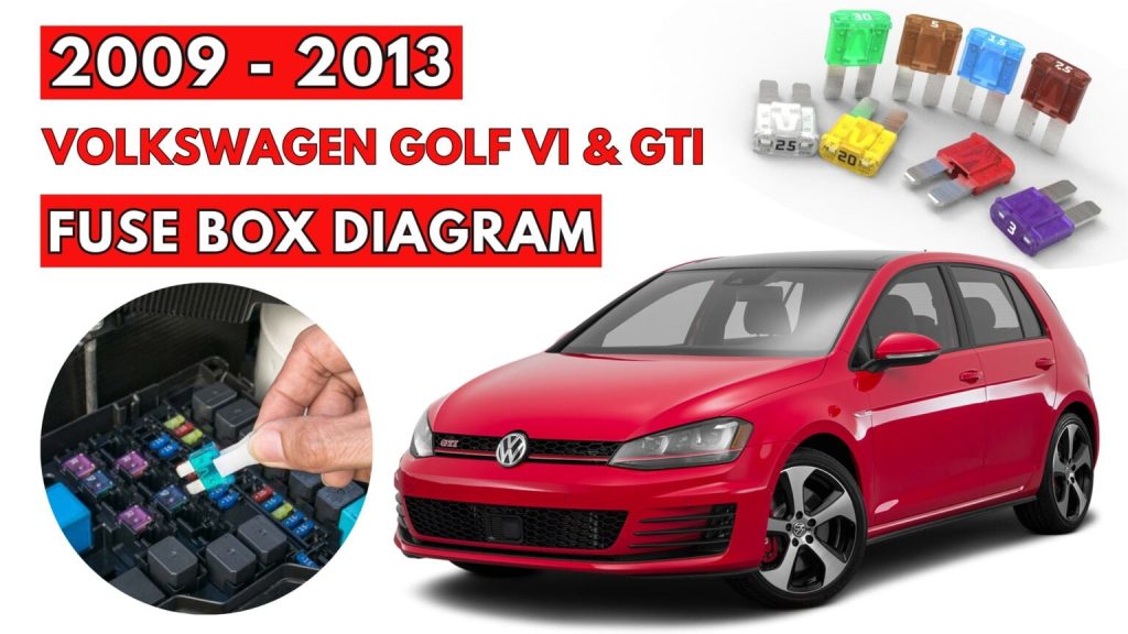
Volkswagen (Golf VI & GTI) (2009 – 2013) Fuse Box Diagrams and Location
Find the locations and schematics of the fuse boxes for the Volkswagen Golf VI and GTI from 2009 to 2013. For fuse replacement and troubleshooting, this site helps you quickly identify and comprehend the electrical system components of your car.
Checking and Replacing Fuses
The fuses are designed to blow before the entire wiring harness is damaged. If any of the electrical components do not operate, a fuse may have blown. If this happens, check and replace the fuses as necessary.
- Switch off the headlights, the ignition, and all electrical consumers.
- Open the appropriate fuse box.
- See diagrams below for details about which fuse to check.
- Remove the fuse using the plastic tweezers located on the fuse box cover.
- Check if the fuse is blown – if the thin metal strip inside is broken, the fuse has blown.
- If the fuse is blown, replace the fuse with a new fuse of the same amperage (same color and same imprint) and the same overall size.
- Replace the cover.
WARNING
High voltage systems in the engine compartment can cause electrical shocks, severe burns, and even death!
- Never touch ignition cables. Never touch other components of the high voltage electronic ignition system.
- Avoid short circuits in the electrical system.
- Never replace a fuse with one that has a higher amp rating. Replace a blown fuse only with a fuse of the same amperage (same color and same imprint) and same overall size.
- Never repair fuses.
- Never replace fuses with a metal strip, a paper clip, or a similar object.
Fuse Box Locations
Instrument Panel Fuse Box
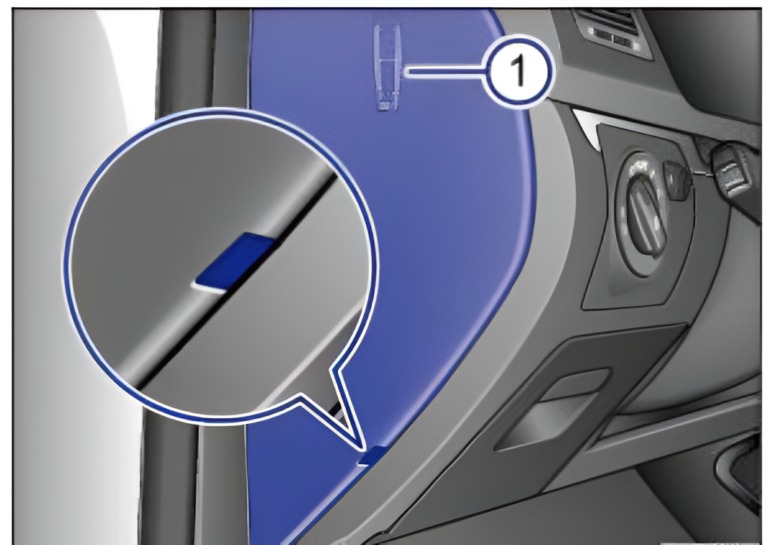
The fuse box is located behind the cover on the driver side edge of the instrument panel.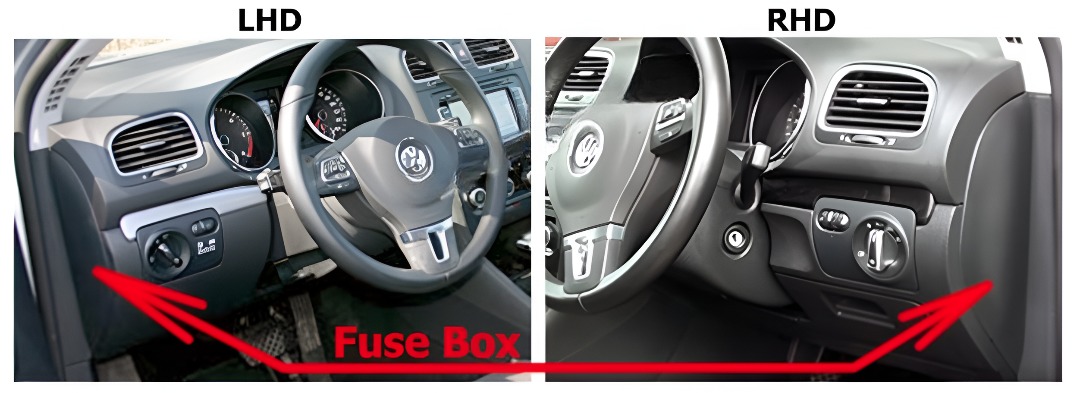
Opening the fuse box in the instrument panel
- Insert a flat object, such as a screwdriver from the vehicle tool kit, into the opening. (magnified view) and carefully lift off the cover.
- On the inside of the cover there are plastic tweezers (1) for removing and inserting fuses.
- To install, guide the cover from the bottom into the instrument panel and push until you can hear it latch into place.
Engine Compartment Fuse Box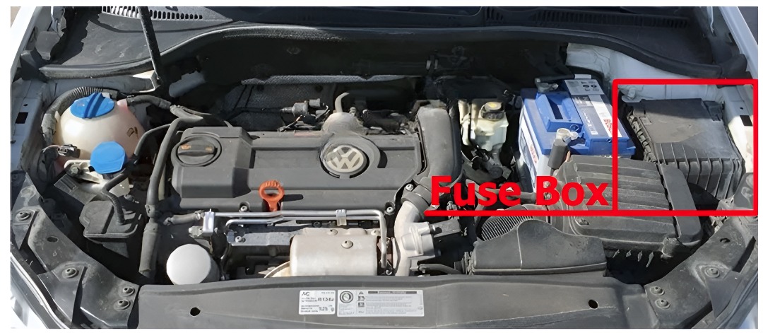
Opening the fuse box in the engine compartment
- Open the engine hood.
- Move the release buttons to unlock the fuse box cover.
- Remove the cover upward.
- To install, place the cover on the fuse box. Slide release buttons against the direction of the arrows until they latch with an audible “click”.
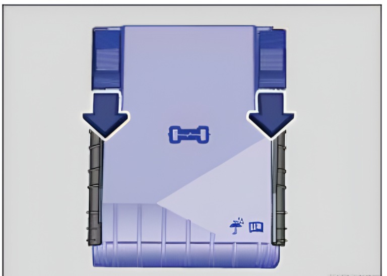
In the engine compartment: Fuse box cover.
Instrument Panel Fuse Box Diagram
2009 – 2013 Volkswagen (Golf VI & GTI)
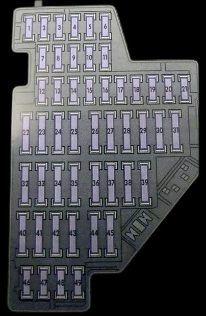
| № | Amp rating (A) | Electrical consumers |
|---|---|---|
| 2; 43; 44; 45 | 10 15 20 15 | Electrical socket for trailer |
| 2; 4 | 10 5 | ABS, ESP |
| 17 | 5 | Anti-tow alarm |
| 3 | 5 | Airbag |
| 2 | 10 | Brake light switch |
| 23 | 20 | Front electric windows |
| 26 | 30 | Rear electric windows |
| 22; 40 | 40 | Blower |
| 25 | 25 | Rear window heating |
| 41 | 20 | Rear wiper |
| 17 | 10 | Interior monitoring |
| 14 | 10 | Air conditioner operating unit |
| 2 | 10 | Combi – instrument |
| 27 | 15 | Fuel pump |
| 34 | 15 | Lumbar support |
| 1 | 10 | Headlight range control |
| 13 | 10 | Rain sensor |
| 14 | 10 | Selector mechanism for the automatic gearbox |
| 36 | 20 | Headlight washer system |
| 33 | 20 | Sliding/tilting roof |
| 37 | 30 | Seat heating |
| 42 | 30 | Socket in front 12V |
| 42 | 20 | Socket in luggage compertment 12V |
| 24 | 20 | Central electronic control unit |
| 12 | 10 | Central locking for front doors |
| 15 | 20 | Central locking for rear doors |
| 42 | 20 | Cigarette lighter |
Engine Compartment Fuse Box Diagram
2009 – 2013 Volkswagen (Golf VI & GTI)
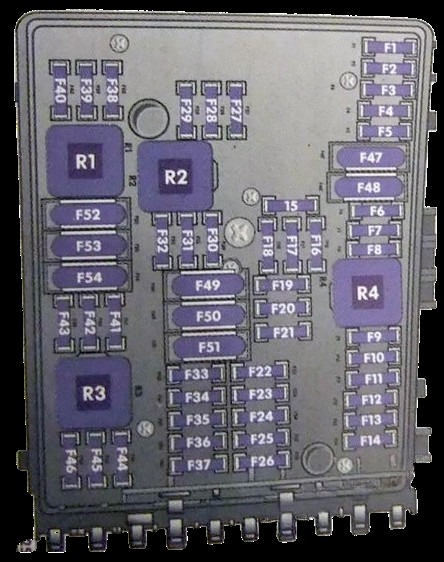
| No | Amp rating (A) | Electrical consumers |
|---|---|---|
| F17 | 15 | Horn |
| F24 | 10 | Radiator fan |
| F26; F16 | 30 | Fog light |
| F26; F16 | 30 | Rear fog light |
| F8 | 25/15 | Radio |
| F26 | 30 | Windscreen washer jets, heated |
| F26 | 30 | Left headlight |
| F16 | 30 | Right headlight |
| F18 | 30 | Sound system |
| F26 | 30 | Left side light |
| F4; F25 | 20 / 40 | ABS, ESP |
| F26 | 30 | Left turn signal |
| F16 | 30 | Right turn signal |
| F16 | 30 | Brake light, right |
| F26 | 30 | Brake light, left |
| F19 | 30 | Windscreen wiper |