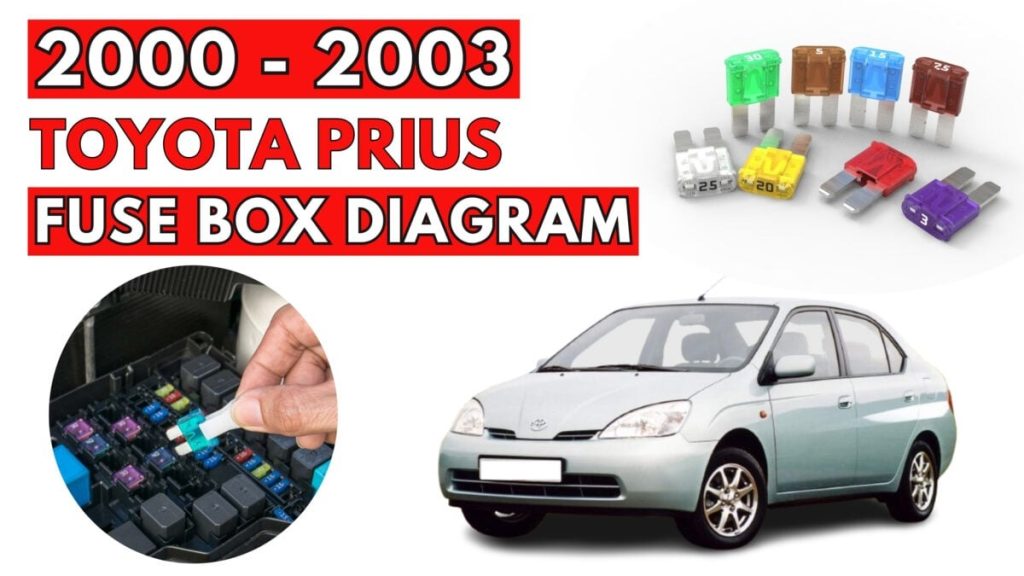
Toyota Prius (2000 – 2003) Fuse Box Location & Diagrams
The first-generation Toyota Prius pioneered hybrid technology, and keeping its complex electrical systems in peak condition is essential for performance. When a component fails, the first step is often checking for a blown fuse to avoid costly shop repairs. This guide offers comprehensive diagrams and specific locations for the 2000–2003 Prius fuse boxes to help you navigate your vehicle’s wiring with confidence.
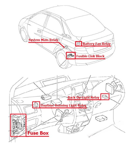
Passenger compartment overview
Passenger Compartment Fuse Box
Toyota Prius (2000 to 2003)
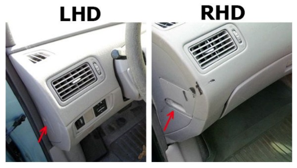
Fuse box location
The fuse box is located on the left side of the instrument panel, behind the cover.
Fuse box diagram
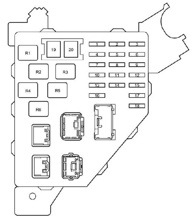
| № | Name | Amp | Circuit |
|---|---|---|---|
| 1 | PANEL | 5 | Audio system, ashtray light, headlight beam level control system, emergency flasher |
| 2 | GAUGE | 10 | Gauge and meter, emergency flasher, rear window defogger, service reminder indicator and warning buzzers, back-up light, power window system, air conditioning system |
| 3 | HTR | 10 | Air conditioning system |
| 4 | TAIL | 7.5 | Parking lights, tail lights, license plate lights, side marker lights |
| 5 | ECU-IG | 5 | Air conditioning system, anti-lock brake system, electric power steering, daytime running light system |
| 6 | STOP | 15 | Stop lights, high mounted stoplights, anti-lock brake system |
| 7 | ACC | 10 | Anti-lock brake system warning light, clock, audio system, multi-information display, shift lock system |
| 8 | WIPER | 30 | Windshield wiper |
| 9 | ECU-B | 7.5 | Air conditioning system, daytime running light system, electric power steering system, hybrid vehicle immobiliser system |
| 10 | CIG | 15 | Power outlet |
| 11 | WASHER | 15 | Washer |
| 12 | DOOR | 30 | Power door lock system |
| 13 | SRS ACC | 10 | SRS airbags, seat belt pretensioners |
| 14 | – | – | – |
| 15 | OBD II | 7.5 | On-board diagnosis system |
| 16 | – | – | – |
| 17 | PWR1 | 20 | Power window system |
| 18 | AM1 | 5 | “ACC”, “CIG”, “SRS ACC”, “WASHER”, “HTR”, “WIPER”, “ECU-IG” and “GAUGE” fuses |
| 19 | DEF | 40 | Rear window defogger |
| 20 | POWER | 30 | Power windows |
| Relay | Description |
|---|---|
| R1 | Ignition (IG1) |
| R2 | Tail lights (TAIL) |
| R3 | Accessory relay (ACC) |
| R4 | – |
| R5 | Power relay (power windows) |
| R6 | Rear window defogger (DEF) |
Fusible Link Block
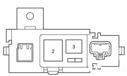
| № | Name | Amp | Circuit |
|---|---|---|---|
| 1 | DC/DC-S | 5 | Inverter and converter |
| 2 | MAIN | 120 | “DC/DC”, “BATT FAN”, “HORN”, “TURN-HAZ”, “DOME”, “THRO”, “EFT”, “AM2”, “ABS NO.2”, “ABS NO.3”, “DC/DC-S”, “HV”, “HEAD” fuses |
| 3 | – | – | – |
Engine Compartment Fuse Boxes
Toyota Prius (2000 to 2003)
Fuse box location
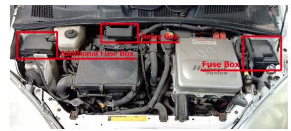
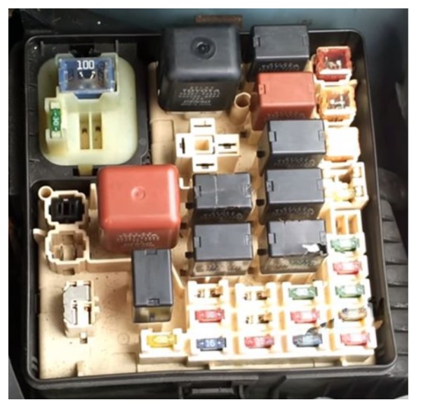
Fuse box diagram
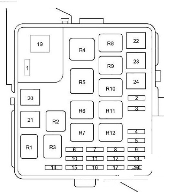
Additional Fuse Box
| № | Name | Amp | Circuit | Relay | Relay Function |
|---|---|---|---|---|---|
| 1 | – | – | – | R1 | with Daytime Running Light: Dimmer (DIM) / without Daytime Running Light: Short Pin |
| 2 | – | – | – | R2 | Headlight (HEAD) |
| 3 | – | – | – | R3 | Fuel pump (Circuit Opening Relay – C/OPN) |
| 4 | CDS FAN | 30 | Air conditioning system | R4 | Heater (HTR) |
| 5 | HORN | 10 | Horn | R5 | with Daytime Running Light: Short Pin |
| 6 | – | – | – | R6 | Engine control unit (EFI) |
| 7 | HEAD HI (RH) | 10 | with Daytime Running Light: Right-hand headlight (high beam) | R7 | Air conditioner compressor clutch (CLR MG) |
| 8 | AM2 | 15 | Starting system, multiport fuel injection system/sequential multiport fuel injection system, hybrid vehicle immobiliser system | R8 | Electric cooling fan (FAN NO.1) |
| 9 | THRO | 15 | Electronic throttle control system | R9 | Electric cooling fan (FAN NO.2) |
| 10 | HEAD (RH) | 10 | Right-hand headlight | R10 | Electric cooling fan (FAN NO.3) |
| 10 | HEAD LO (RH) | 10 | with Daytime Running Light: Right-hand headlight (low beam) | R11 | Ignition (IG2) |
| 11 | HEAD HI (LH) | 10 | with Daytime Running Light: Left-hand headlight (high beam) | R12 | Horn |
| 12 | BATT FAN | 10 | Battery cooling fan | – | – |
| 13 | ABS NO.3 | 20 | Hydraulic brake booster | – | – |
| 14 | HV | 20 | Hybrid system | – | – |
| 15 | EFI | 15 | Multiport fuel injection system / Sequential multiport fuel injection system | – | – |
| 16 | HEAD (LH) | 10 | Left-hand headlight | – | – |
| 16 | HEAD LO (LH) | 10 | with Daytime Running Light: Left-hand headlight (low beam) | – | – |
| 17 | DOME | 15 | Audio system, multi-information display, interior light, trunk light, power window system, wireless remote control system | – | – |
| 18 | TURN-HAZ | 10 | Turn signal lights, Emergency flasher | – | – |
| 19 | DC/DC | 100 | ACC relay, IG1 relay, TAIL relay, “ABS NO.4”, “HTR1”, “HTR2”, “ABS NO.1”, “HTR3”, “EMPS”, “CDS FAN”, “RDI”, “HTR”, “OBD II”, “ECU-B”, “STOP”, “PWR1”, “POWER”, “DOOR”, “DEF”, “AM1” fuses | – | – |
| 20 | HEAD | 30 | with Daytime Running Light: Daytime running light system | – | – |
| 20 | SHORT PIN | – | without Daytime Running Light: Short pin | – | – |
| 21 | – | – | – | – | – |
| 22 | HTR | 50 | Air conditioning system |
Additional Fuse Box
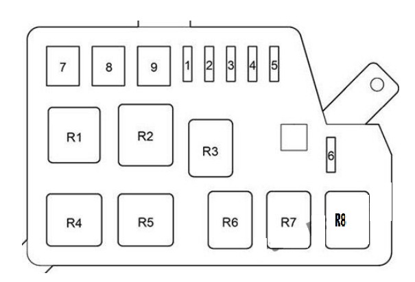
| № | Name | Amp | Circuit | Relay | Relay Function |
|---|---|---|---|---|---|
| 1 | ABS NO.4 | 10 | Anti-lock brake system | R1 | Daytime running light (DRL) |
| 2 | HTR NO.1 | 30 | Air conditioning system | R2 | Anti-lock brake system (ABS SOL) |
| 3 | – | – | – | R3 | A/C Water Pump (A/C W/P) |
| 4 | HTR NO.2 | 30 | Air conditioning system | R4 | Electric power steering (EMPS) |
| 5 | – | – | – | R5 | Air conditioning system (HTR3) |
| 6 | DRL | 7.5 | Daytime running light system | R6 | – |
| 7 | HTR3 | 50 | Air conditioning system | R7 | Air conditioning system (HTR1) |
| 8 | EM PS | 50 | Electric power steering | R8 | Air conditioning system (HTR2) |
| 9 | ABS NO.1 | 40 | Anti-lock brake system | – | – |
Relay Box
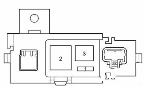
| № | Relay |
|---|---|
| R1 | (HYDRO MTR NO.1) |
| R2 | (HYDRO MTR NO.2) |
| R3 | – |
| R4 | (IGCT) |