Ford F-250 (2004 – 2007) Fuse Box Location & Diagrams
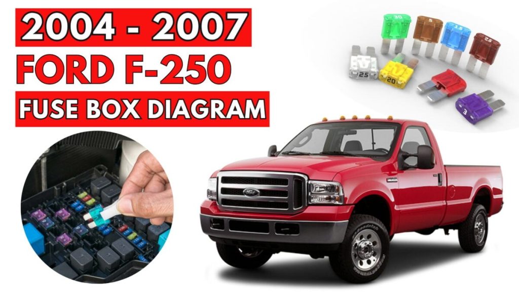
Looking for your Ford F-250 fuse box? This comprehensive guide for 2004–2007 models provides detailed diagrams, exact locations, and helpful tips to quickly identify and replace fuses, keeping your truck’s electrical system running smoothly.
Fuse Box Locations
Passenger Compartment
The fuse panel is located below and to the left of the steering wheel by the brake pedal. Remove the panel cover to access the fuses.
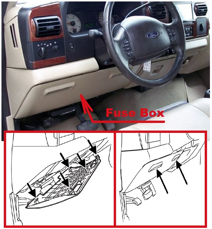
- To remove the fuse panel cover, pull the panel downward by the finger slots on top of the panel. When the top clips of the panel disengage, let the panel fall easily.
- To remove a fuse use the fuse puller tool provided on the fuse panel cover.
- To reinstall the cover, align and engage the two hooked clips at the bottom of the cover onto the instrument panel, then lift the panel and press the top clips firmly into place.
Always replace the cover to the passenger compartment fuse panel before reconnecting the battery.
Engine Compartment
The power distribution box is located in the engine compartment. The power distribution box contains high-current fuses that protect your vehicle’s main electrical systems from overloads.
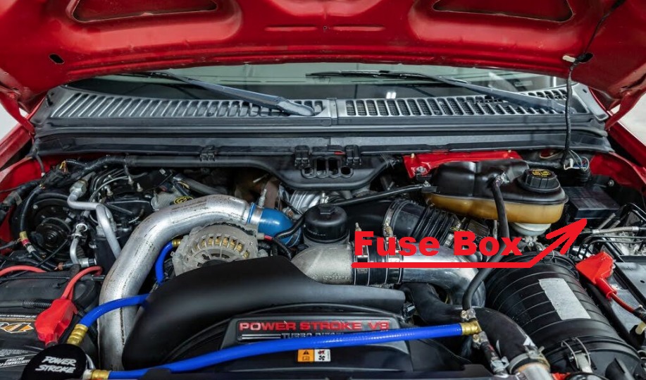
- Always disconnect the battery before servicing high current fuses.
- To reduce risk of electrical shock, always replace the cover to the Power Distribution Box before reconnecting the battery or refilling fluid reservoirs.
Passenger Compartment Fuse Box Diagram
Ford F-250 (2004)
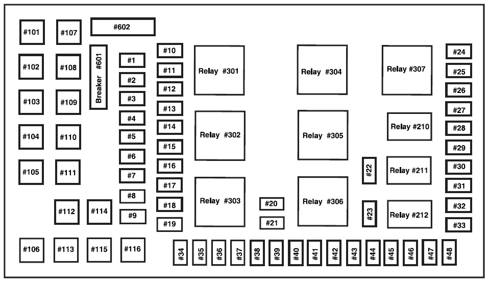
The fuses are coded as follows.
| Fuse/Relay Location | Fuse Amp Rating | Passenger Compartment Fuse Panel Description |
| 1 | 15A* | Adjustable pedals |
| 2 | — | Not used |
| 3 | — | Not used |
| 4 | 20A* | Power point – instrument panel |
| 5 | — | Not used |
| 6 | 20A* | Trailer tow turn/stop relay |
| 7 | 30A* | High beam headlamps/Flash to pass |
| 8 | 15A* | Backup lamps (Diesel engine only) |
| 9 | 20A* | Heated mirrors |
| Fuse/Relay Location | Fuse Amp Rating | Passenger Compartment Fuse Panel Description |
| 10 | 10A* | A/C clutch |
| 11 | 20A* | Radio (main) |
| 12 | 20A* | Cigar lighter / OBD II |
| 13 | 5A* | Power mirrors/switches |
| 14 | 15A* | Daytime running lamps (DRL) |
| 15 | — | Not used |
| 16 | — | Not used |
| 17 | 15A* | Exterior lamps |
| 18 | 20A* | Turn lamps/Brake on-off switch (high) |
| 19 | 10A* | Body security module/4×4 module |
| 20 | 10A* | Fuel Injection Control Module (FICM) relay (Diesel engine only) |
| 21 | — | Not used |
| 22 | 20A* | Engine control |
| 23 | 20A* | Engine control (gasoline engine only), Climate control (Diesel engine only) |
| 24 | 2A* | Brake pressure switch/Speed control |
| 25 | 10A* | 4-Wheel Anti-lock Brake System (4WABS) module, Variable Fan Control (VFC) (Diesel engine only) |
| 26 | 10A* | Air bags |
| 27 | 15A* | Ignition switch Run feed |
| 28 | 10A* | EATC module/Front blower relay coil |
| 29 | 10A* | Customer access |
| 30 | 15A* | Highbeam headlamps |
| Fuse/Relay Location | Fuse Amp Rating | Passenger Compartment Fuse Panel Description |
| 31 | 15A* | Clutch interlock switch (manual transmissions only), Transmission range sensor (automatic transmissions only) then to starter relay coil (all transmissions), 4×4 |
| 32 | 5A* | Radio (start) |
| 33 | 15A* | Front wiper |
| 34 | 10A* | Brake on-off switch |
| 35 | 10A* | Instrument cluster |
| 36 | 10A* | PCM Memory |
| 37 | 15A* | Horn |
| 38 | 20A* | Trailer tow park lamps |
| 39 | 15A* | Trailer tow back-up lamps |
| 40 | 20A* | Fuel pump |
| 41 | 10A* | Instrument cluster |
| 42 | 15A* | Delayed accessory |
| 43 | 10A* | Fog lamps |
| 44 | — | Not used |
| 45 | 10A* | Ignition switch Run/Start feed |
| 46 | 10A* | Left-hand lowbeam |
| 47 | 10A* | Right-hand lowbeam |
| 48 | — | Not used |
| 101 | 30A** | Trailer tow electric brake |
| 102 | 30A** | Door locks/Body security module |
| 103 | 50A** | Ignition switch (gasoline engine only), FICM power (Diesel engine only) |
| 104 | 40A** | Heated backlight |
| 105 | 30A** | Fuel heater (Diesel engine only) |
| 106 | 30A** | Front wiper main |
| 107 | 40A** | Front blower motor |
| Fuse/Relay Location | Fuse Amp Rating | Passenger Compartment Fuse Panel Description |
| 108 | — | Not used |
| 109 | 30A** | Heated seats |
| 110 | 50A** | Ignition switch |
| 111 | 30A** | 4WD/Shift on the fly |
| 112 | 30A** | Left-hand power seats |
| 113 | 30A** | Starter motor |
| 114 | 30A** | Right-hand power seats |
| 115 | 20A** | Trailer tow battery charge |
| 116 | 30A** | Ignition switch |
| 601 | 30A CB*** | Window motors, Moonroof |
| 602 | 60A** | 4WABS module |
| 210 | — | Not used |
| 211 | — | Backup lamps relay (Diesel engine only) |
| 212 | — | Not used |
| 301 | — | Front blower motor relay |
| 302 | — | Powertrain Control Module (PCM) relay |
| 303 | — | Fuel heater relay (Diesel engine only) |
| 304 | — | Heated backlight relay |
| 305 | — | Trailer tow battery charge relay |
| 306 | — | Delayed accessory relay |
| 307 | — | Starter relay |
| * Mini Fuses ** Maxi Fuses ***Circuit Breaker | ||
Ford F-250 (2005, 2006 and 2007)
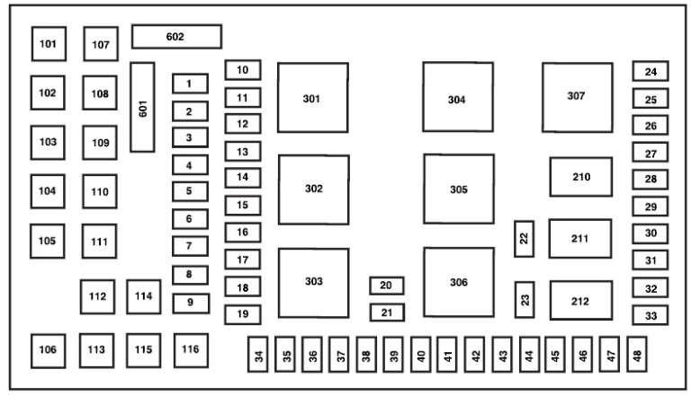
The fuses are coded as follows.
| Fuse/Relay Location | Fuse Amp Rating | Passenger Compartment Fuse Panel Description |
| 1 | 15A* | Adjustable pedals |
| 2 | 10A* | Cluster |
| 3 | 10A* | Upfitter #3 |
| 4 | 20A* | Power point (Instrument panel) |
| 5 | 10A* | Upfitter #4 |
| 6 | — | Not used |
| 7 | 30A* | High beam headlamps, Flash-to-pass |
| 8 | 20A* | Back-up lamps |
| 9 | — | Not used |
| 10 | — | Not used |
| 11 | 20A* | Radio (Main) |
| 12 | 20A* | Cigar lighter, OBD II |
| 13 | 5A* | Power mirrors |
| 14 | — | Not used |
| Fuse/Relay Location | Fuse Amp Rating | Passenger Compartment Fuse Panel Description |
| 15 | — | Not used |
| 16 | — | Not used |
| 17 | 15A* | Exterior lamps |
| 18 | 20A* | Flasher, Brake On-Off (BOO) lamps |
| 19 | 10A* | Body Security Module (BSM) (Security) |
| 20 | 15A* | Trailer tow Electric Brake Controller (EBC) |
| 21 | 20A* | Heated seats |
| 22 | 20A* | Engine control |
| 23 | 20A* | Engine control (gasoline engine only)/Climate control (Diesel engine only) |
| 24 | 15A* | Tow haul, Blower relay, Electronic Automatic Temperature Control (EATC) |
| 25 | — | Not used |
| 26 | 10A* | Air bags |
| 27 | 15A* | Ignition switch RUN feed |
| 28 | 10A* | Trailer tow EBC logic |
| 29 | 10A* | Customer access |
| 30 | 15A* | High beam headlamps |
| 31 | 15A* | 4×4 |
| 32 | 5A* | Radio (start) |
| 33 | 15A* | Cluster, 4×4, Wipers |
| 34 | 10A* | BOO switch (Low current) |
| 35 | 10A* | Instrument cluster |
| 36 | — | Not used |
| 37 | 15A* | Horn |
| 38 | 20A* | Trailer tow park lamps |
| 39 | 15A* | Heated mirrors |
| Fuse/Relay Location | Fuse Amp Rating | Passenger Compartment Fuse Panel Description |
| 40 | 20A* | Fuel pump |
| 41 | 10A* | Instrument cluster |
| 42 | 15A* | Delayed accessory |
| 43 | 10A* | Fog lamps |
| 44 | — | Not used |
| 45 | 10A* | Ignition switch RUN/START feed |
| 46 | 10A* | Left-hand low beam headlamp |
| 47 | 10A* | Right-hand low beam headlamp |
| 48 | — | Not used |
| 101 | 30A** | Trailer tow EBC |
| 102 | 30A** | BSM (Door locks) |
| 103 | 30A** | Ignition switch |
| 104 | — | Not used |
| 105 | — | Not used |
| 106 | — | Not used |
| 107 | 20A** | Trailer tow battery charge |
| 108 | 30A** | Upfitter #1 |
| 109 | 30A** | Upfitter #2 |
| 110 | 30A** | Ignition switch |
| 111 | — | Not used |
| 112 | 30A** | Power seat (Driver) |
| 113 | 30A** | Starter |
| 114 | 30A** | Power seat (Passenger) |
| 115 | 20A** | Upfitter control |
| 116 | 30A** | Ignition switch |
| 210 | — | Not used |
| 211 | 1⁄2 ISO relay | Back-up lamps |
| 212 | — | Not used |
| 301 | Full ISO relay | Trailer tow battery charge |
| 302 | Full ISO relay | Powertrain Control Module (PCM) |
| 303 | — | Not used |
| Fuse/Relay Location | Fuse Amp Rating | Passenger Compartment Fuse Panel Description |
| 304 | — | Not used |
| 305 | Full ISO relay | Upfitter control |
| 306 | Full ISO relay | Delayed accessory |
| 307 | Full ISO relay | Starter |
| 601 | 30A circuit breaker | Delayed accessory, Power windows, Moonroof |
| 602 | — | Not used |
| * Mini fuse ** Cartridge fuse | ||
Engine Compartment Fuse Box Diagram
Ford F-250 (2005, 2006 and 2007)
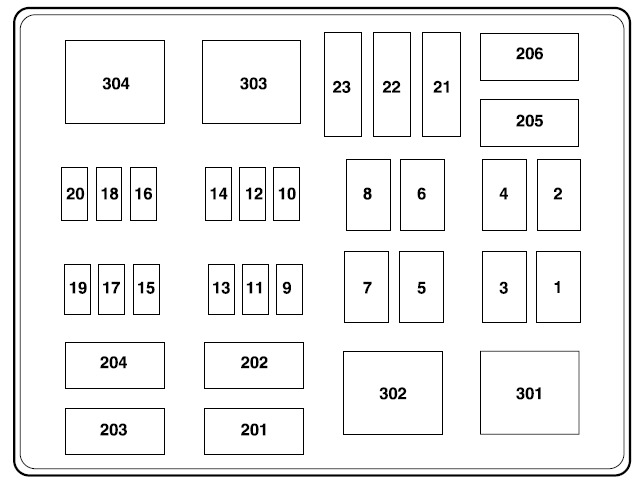
The high-current fuses and relays are coded as follows.
| Fuse/Relay Location | Fuse Amp Rating | Power Distribution Box Description |
| 1 | 30A* | Wipers |
| 2 | 40A* | Blower |
| 3 | 30A* | Electronic Shift on the Fly (ESOF) |
| 4 | — | Not used |
| 5 | 50A* | Injector Driver Module (IDM) (Diesel engine only) |
| 6 | — | Not used |
| 7 | 30A*
— | Horizontal Fuel Conditioner Module (HFCM) (Diesel engine only) (2005 and 2006) Not Used (2007) |
| 8 | — — | Not used (2005) Shunt (2006 and 2007) |
| 9 | 20A** | Trailer tow turn signals |
| 10 | 10A** | Powertrain Control Module (PCM) keep alive power, Canister vent solenoid (gasoline engine only) |
| 11 | 10A** | Anti-lock Brake System (ABS) |
| Fuse/Relay Location | Fuse Amp Rating | Power Distribution Box Description |
| 12 | 2A** | Brake pressure switch |
| 13 | 15A** | Daytime Running Lamps (DRL) |
| 14 | — | Not used |
| 15 | 15A** | IDM logic (Diesel engine only) |
| 16 | — | Not used |
| 17 | 10A** | A/C clutch |
| 18 | 10A** | IDM relay (Diesel engine only) |
| 19 | — | Not used |
| 20 | 10A** | Trailer tow back-up lamps |
| 21 | — | Not used |
| 22 | 60A*** | ABS (Coils) |
| 23 | 60A*** | ABS (Pump) |
| 201 | 1⁄2 ISO relay | Trailer tow right turn signal/stop lamp |
| 202 | 1⁄2 ISO relay | Trailer tow left turn signal/stop lamp |
| 203 | 1⁄2 ISO relay | A/C clutch |
| 204 | — | Not used |
| 205 | 1⁄2 ISO relay | DRL #1 |
| 206 | 1⁄2 ISO relay | DRL #2 |
| 301 | Full ISO relay | DRL #3 |
| 302 | Full ISO relay – | HFCM (2005 and 2006) Not used (2007) |
| 303 | Full ISO relay | Blower |
| 304 | High-current relay | IDM (Diesel engine only) |
| * Cartdrige Fuse ** Mini Fuses *** Maxi fuse | ||
Auxiliary Relay Box
Ford F-250 (2006 and 2007)
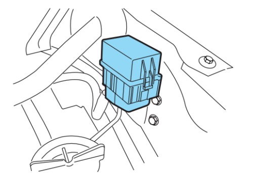
An auxiliary relay box is located in the left-hand front side of the engine compartment. This box contains relays for the Electronic Shift On the Fly (ESOF) system.