Dodge Challenger (2009 – 2014) Fuse Box Location and Diagrams
This blog shows 2009–2014 Dodge Challenger fuse box diagrams and locations. This breakdown makes it easier to identify everything you need to fix a circuit or check a fuse.
Fuse Box Locations
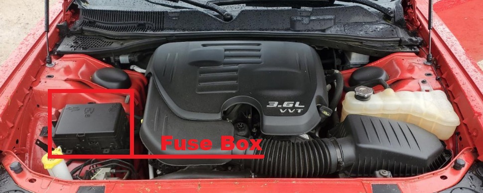
Integrated Power Module
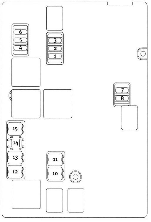
The Integrated Power Module (IPM) is located in the engine compartment, on the passenger side.
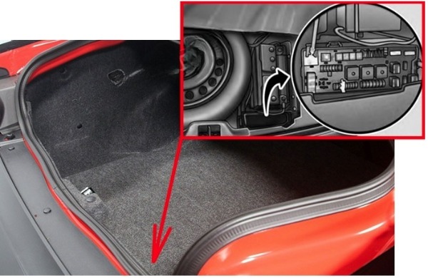
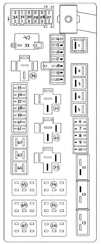
Rear Power Distribution Center
There is also a power distribution center located in the trunk under the spare tire access panel.M
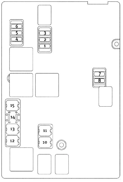
Integrated Power Module Diagram
Dodge Challenger (2009 and 2010)
| Cavity | Cartridge Fuse | Mini-Fuse | Description |
|---|
| 1 | — | 15 Amp Blue | Washer Motor |
| 2 | — | 25 Amp Natural | Powertrain Control Module (PCM)/NGS Module Feed (Batt) |
| 3 | — | 25 Amp Natural | Ignition Run/Start |
| 4 | — | 25 Amp Natural | EGR Solenoid/Alternator |
| 5 | — | — | — |
| 6 | — | 25 Amp Natural | Ignition Coils/Injectors |
| 7 | — | — | — |
| 8 | — | 30 Amp Green | Starter |
| 9 | — | — | — |
| 10 | 30 Amp Pink | — | Windshield Wiper |
| 11 | 30 Amp Pink | — | Anti-Lock Brake System (ABS) Valves |
| 12 | 40 Amp Green | — | Radiator Fan Lo/High |
| 13 | 50 Amp Red | — | Anti-Lock Brake System (ABS) Pump Motor |
| 14 | — | — | — |
| 15 | 50 Amp Red | — | Radiator Fan |
| 16 | — | — | — |
| 17 | — | — | — |
| 18 | — | — | — |
| 19 | — | — | — |
| 20 | — | — | — |
| 21 | — | — | — |
| 22 | — | — | — |
Dodge Challenger (2011 to 2014)
| Cavity | Cartridge Fuse | Mini-Fuse | Description |
|---|
| 1 | — | 15 Amp Blue | Washer Motor |
| 2 | — | 25 Amp Natural | Powertrain Control Module (PCM)/NGS Module Feed (Batt) |
| 3 | — | 25 Amp Natural | Ignition Run/Start |
| 4 | — | 25 Amp Natural | EGR Solenoid/Alternator |
| 5 | — | 15 Amp Blue | Powertrain Control Module |
| 6 | — | 25 Amp Natural | Ignition Coils/Injectors |
| 7 | — | 25 Amp Natural | Headlamp Washer Relay – If Equipped |
| 8 | — | 30 Amp Green | Starter |
| 9 | — | — | — |
| 10 | 30 Amp Pink | — | Windshield Wiper |
| 11 | 30 Amp Pink | — | Anti-Lock Brake System (ABS) Valves |
| 12 | 40 Amp Green | — | Radiator Fan Lo/High |
| 13 | 50 Amp Red | — | Anti-Lock Brake System (ABS) Pump Motor |
| 14 | — | — | — |
| 15 | 50 Amp Red | — | Radiator Fan |
| 16 | — | — | — |
| 17 | — | — | — |
| 18 | — | — | — |
| 19 | — | — | — |
| 20 | — | — | — |
| 21 | — | — | — |
| 22 | — | — | — |
Rear Power Distribution Center Diagram
Dodge Challenger (2009 and 2010)
| Cavity | Cartridge Fuse | Mini-Fuse | Description |
|---|
| 1 | 60 Amp Yellow | | Ignition Off Draw (IOD) Cavity 1 of the Rear Power Distribution Center contains a black IOD fuse needed for vehicle processing during assembly. The service replacement part is a 60 Amp yellow cartridge fuse. |
| 2 | 40 Amp Green | — | Integrated Power Module (IPM) |
| 3 | — | — | — |
| 4 | 40 Amp Green | — | Integrated Power Module (IPM) |
| 5 | 30 Amp Pink | — | Heated Seats – If Equipped |
| 6 | — | 20 Amp Yellow | Fuel Pump |
| 7 | — | 15 Amp Blue | Audio Amplifier – If Equipped |
| 8 | | 15 Amp Blue | Diagnostic Link Connector (DLC)/ Wireless Control Module (WCM)/Wireless Ignition Node (WIN) |
| 9 | — | 20 Amp Yellow | Power Outlet |
| 10 | — | 25 Amp Natural | Vacuum Pump – If Equipped |
| 11 | 25 Amp circuit breaker | — | The cluster and the driver seat switch (Cavities 11, 12, and 13 contain self-resetting fuses (circuit breakers) that are only serviceable by an authorized dealer) |
| 12 | 25 Amp circuit breaker | — | The passenger seat switch (Cavities 11, 12, and 13 contain self-resetting fuses (circuit breakers) that are only serviceable by an authorized dealer) |
| 13 | 25 Amp circuit breaker | — | The door modules, the driver power window switch, and the passenger power window switch (Cavities 11, 12, and 13 contain self-resetting fuses (circuit breakers) that are only serviceable by an authorized dealer) |
| 14 | — | 10 Amp Red | AC Heater Control/Cluster/Security Module – If Equipped |
| 15 | — | 20 Amp Yellow | Active Damper – If Equipped |
| 16 | — | 20 Amp Yellow | Heated Seat Module – If Equipped |
| 17 | — | 20 Amp Yellow | Instrument Cluster |
| 18 | — | 20 Amp Yellow | Cigar Lighter (Instrument Panel) |
| 19 | — | 10 Amp Red | Stop Lights |
| 20 | — | — | — |
| 21 | — | — | — |
| 22 | — | — | — |
| 23 | — | — | — |
| 24 | — | — | — |
| 25 | — | — | — |
| 26 | — | — | — |
| 27 | — | 10 Amp Red | Occupant Restraint Controller (ORC) |
| 28 | — | 15 Amp Blue | Ignition Run, AC Heater Control/ Occupant Restraint Controller (ORC) |
| 29 | | 5 Amp Tan | Cluster/Electronic Stability Control (ESC)/ Powertrain Control Module (PCM)/STOP LIGHT Switch |
| 30 | — | 10 Amp Red | Door Modules/Power Mirrors/Steering Control Module (SCM) |
| 31 | — | — | — |
| 32 | — | — | — |
| 33 | — | — | — |
| 34 | — | — | — |
| 35 | — | 5 Amp Tan | Antenna Module – If Equipped/Power Mirrors |
| 36 | — | 25 Amp Natural | Hands-Free Phone – If Equipped/Radio/ Amplifier Feed |
| 37 | — | 15 Amp Blue | Transmission |
| 38 | — | 10 Amp Red | Cargo Light/Vehicle Information Module – If Equipped |
| 39 | — | 10 Amp Red | Heated Mirrors – If Equipped |
| 40 | — | 5 Amp Orange | Auto Inside Rearview Mirror/Heated Seats – If Equipped/Switch Bank |
| 41 | — | — | — |
| 42 | 30 Amp Pink | — | Front Blower Motor |
| 43 | 30 Amp Pink | — | Rear Window Defroster |
| 44 | 20 Amp Blue | — | Amplifier/Sunroof – If Equipped |
Dodge Challenger (2011 to 2014)
| Cavity | Cartridge Fuse | Mini-Fuse | Description |
|---|
| 1 | 60 Amp Yellow | | Ignition Off Draw (IOD) Cavity 1 of the Rear Power Distribution Center contains a black IOD fuse needed for vehicle processing during assembly. The service replacement part is a 60 Amp yellow cartridge fuse. |
| 2 | 40 Amp Green | — | Integrated Power Module (IPM) |
| 3 | — | — | — |
| 4 | 40 Amp Green | — | Integrated Power Module (IPM) |
| 5 | 30 Amp Pink | — | Heated Seats – If Equipped |
| 6 | — | 20 Amp Yellow | Fuel Pump |
| 7 | — | 15 Amp Blue | Audio Amplifier – If Equipped |
| 8 | | 15 Amp Blue | Diagnostic Link Connector (DLC)/ Wireless Control Module (WCM)/Wireless Ignition Node (WIN) |
| 9 | — | 20 Amp Yellow | Power Outlet |
| 10 | — | — | — |
| 11 | 25 Amp circuit breaker | — | The cluster and the driver seat switch (Cavities 11, 12, and 13 contain self-resetting fuses (circuit breakers) that are only serviceable by an authorized dealer) |
| 12 | 25 Amp circuit breaker | — | The passenger seat switch (Cavities 11, 12, and 13 contain self-resetting fuses (circuit breakers) that are only serviceable by an authorized dealer) |
| 13 | 25 Amp circuit breaker | — | The door modules, the driver power window switch, and the passenger power window switch (Cavities 11, 12, and 13 contain self-resetting fuses (circuit breakers) that are only serviceable by an authorized dealer) |
| 14 | — | 10 Amp Red | AC Heater Control/Cluster/Security Module – If Equipped |
| 15 | — | — | — |
| 16 | — | — | — |
| 17 | — | 20 Amp Yellow | Cluster |
| 18 | — | 20 Amp Yellow | Selectable Power Outlet |
| 19 | — | 10 Amp Red | Stop Lights |
| 20 | — | — | — |
| 21 | — | — | — |
| 22 | — | — | — |
| 23 | — | — | — |
| 24 | — | — | — |
| 25 | — | — | — |
| 26 | — | — | — |
| 27 | — | 10 Amp Red | Occupant Restraint Controller (ORC) |
| 28 | — | 10 Amp Red | Ignition Run |
| 29 | | 5 Amp Tan | Cluster/Electronic Stability Control (ESC)/ Powertrain Control Module (PCM)/STOP LIGHT Switch |
| 30 | — | 10 Amp Red | Door Modules/Power Mirrors/Steering Control Module (SCM) |
| 31 | — | — | — |
| 32 | — | — | — |
| 33 | — | — | — |
| 34 | — | — | — |
| 35 | — | 5 Amp Tan | Antenna Module – If Equipped/Power Mirrors |
| 36 | — | 25 Amp Natural | Hands-Free Phone – If Equipped/Radio/ Amplifier Feed |
| 37 | — | 15 Amp Blue | Transmission |
| 38 | — | 10 Amp Red | Cargo Light/Vehicle Information Module – If Equipped |
| 39 | — | 10 Amp Red | Heated Mirrors – If Equipped |
| 40 | — | 5 Amp Orange | Auto Inside Rearview Mirror/Heated Seats – If Equipped/Switch Bank |
| 41 | — | — | — |
| 42 | 30 Amp Pink | — | Front Blower Motor |
| 43 | 30 Amp Pink | — | Rear Window Defroster |
| 44 | 20 Amp Blue | — | Amplifier/Sunroof – If Equipped |