Ford Transit (2006 – 2013) Fuse Box Diagrams and Location
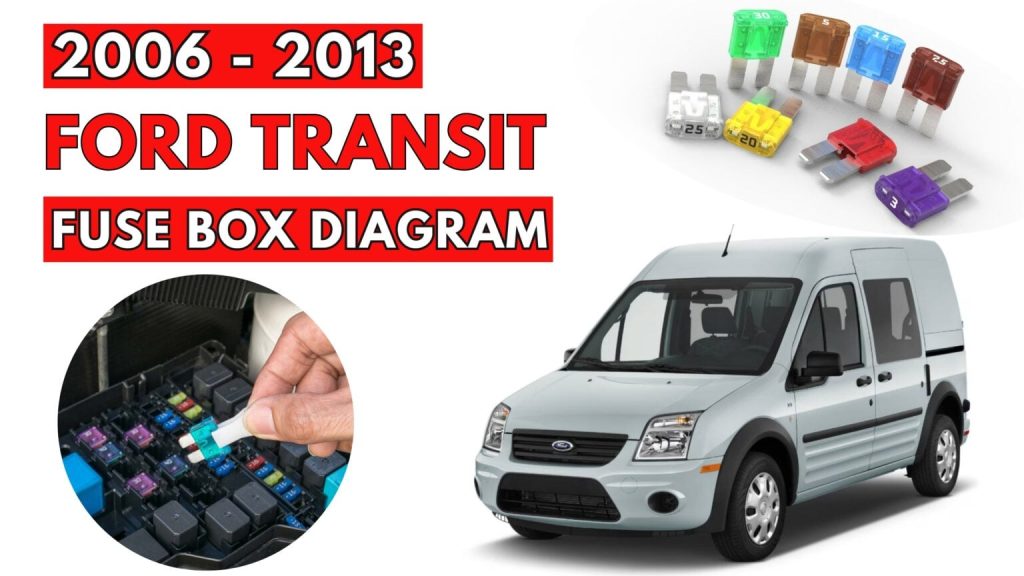
View the locations and diagrams of the fuse boxes for Ford Transit (2006–2013). This blog provides straightforward layout and graphics to help you locate and replace blown fuses. useful for do-it-yourself diagnosis and fixes.
Changing a Fuse
WARNINGS
- Do not modify the electrical system of your vehicle in any way. Have repairs to the electrical system and the replacement of relays and high current fuses carried out by properly trained technicians.
- Switch the ignition and all electrical equipment off before touching or attempting to change a fuse.
CAUTION
Fit a replacement fuse with the same rating as the one you have removed.
Note:
- You can identify a blown fuse by a break in the filament.
- All fuses, except high current fuses, are a push fit.
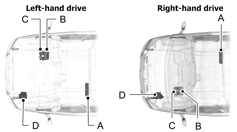
Fuse Box Locations
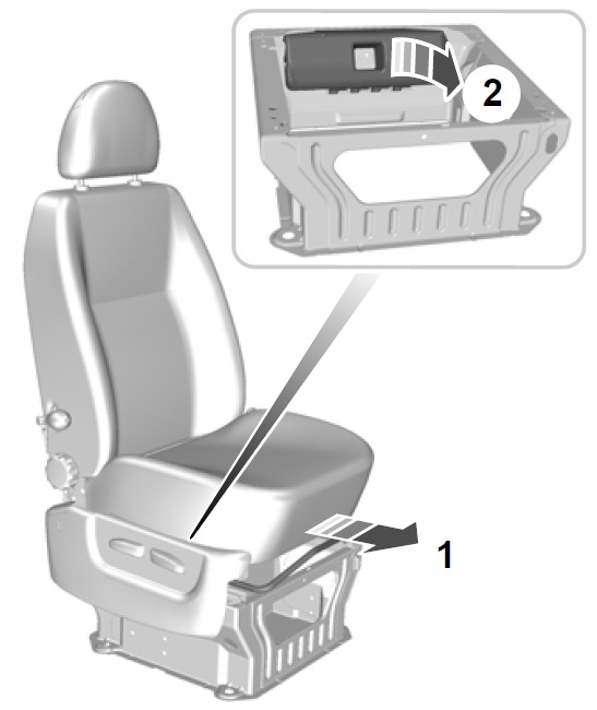
- A – Pre-fuse box
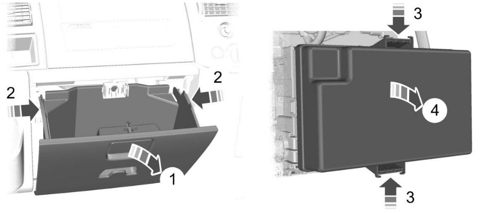
- B – Standard relay box
- C – Passenger compartment junction box
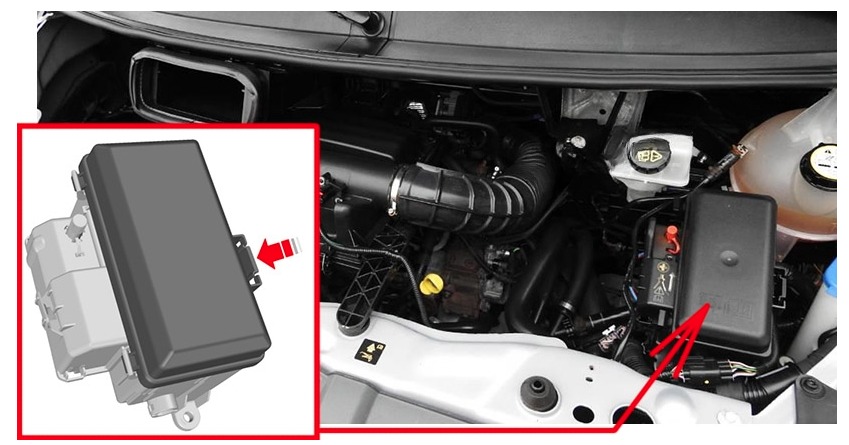
- D – Engine compartment junction box
Pre-fuse box
It is located under the driver’s seat.
Standard relay box
It is located behind the glove compartment.
Passenger compartment junction box
It is located behind the glove compartment.
Engine compartment junction box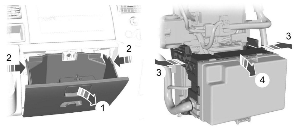
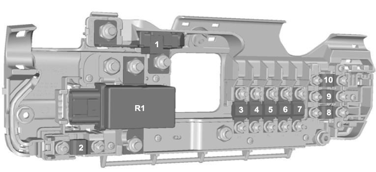
Pre-fuse Box Diagram
Ford Transit (2006 to 2010, 2012 to 2013)
| Fuse | Ampere rating | Colour | Circuits protected |
| 1 | 350 | grey | Starter motor and alternator |
| 2 | 60 | yellow | Passenger junction box power supply – start relevant |
| Fuse | Ampere rating | Colour | Circuits protected |
| 3 | 100 | blue | Engine junction box power supply – non-start relevant |
| 4 | 40 | green | Heated front screen right-hand side |
| 5 | 100 | blue | Standard relay box power supply – non-start relevant |
| 6 | 40 | green | Heated front screen left-hand side |
| 7 | 60 | yellow | Passenger junction box power supply – non- start relevant |
| 8 | 60 | yellow | Customer connection point |
| 9 | 60 | yellow | Customer connection point |
| 10 | 60 | yellow | Customer connection point |
| Relay | Circuits switched |
| R1 | Battery disconnect switch |
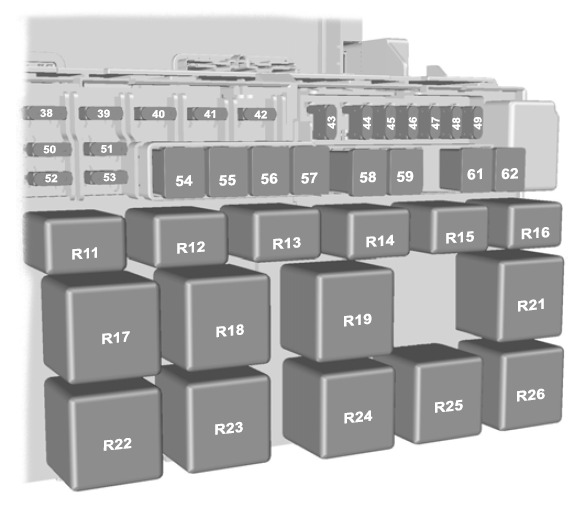
Standard Relay Box Diagram
Ford Transit (2006 to 2010, 2012 to 2013)
| Fuse | Ampere rating | Colour | Circuits protected |
| 38 | 20 | yellow | Rear window wiper |
| 39 | 10 | red | Front and rear air conditioning control |
| 40 | 5 | tan | Relay coils supply |
| 41 | 5 | tan | Tachograph |
| Fuse | Ampere rating | Colour | Circuits protected |
| 42 | 5 | tan | Headlamp levelling, master light switch (KL15) |
| 43 | 20 | yellow | Heated front seats |
| 44 | 20 | yellow | Horn |
| 45 | 20 | yellow | Auxiliary power point front |
| 46 | 10 | red | Heated door mirrors, if CAT 1 fitted |
| 47 | 20 | yellow | Cigar lighter |
| 48 | 5 | tan | Relay coils supply, power mirrors |
| 49 | 20 | yellow | Auxiliary power point rear |
| 50 | 10 | red | Main beam left-hand side |
| 51 | 10 | red | Main beam right-hand side |
| 52 | 10 | red | Dipped beam left-hand side |
| 53 | 10 | red | Dipped beam right-hand side |
| 54 | 30 | pink | Pre-fuse for dipped beam, main beam, daytime running lamps, tachograph, fuel- fired booster heater blower |
| 55 | 40 | green | Heater blower motor |
| 56 | 20 | yellow | Power windows |
| 57 | 30 | pink | Rear heater blower motor |
| 58 | 30 | pink | Front wiper motor |
| 59 | 30 | pink | Heated rear window, heated door mirrors |
| 60 | – | – | Not used |
| 61 | 60 | yellow | Ignition relay (KL15 #1) |
| 62 | 60 | yellow | Ignition relay (KL15 #2) |
| Relay | Circuits switched |
| R11 | Headlamp dip beam |
| Relay | Circuits switched |
| R12 | Heated door mirrors (if CAT 1 alarm is fitted) |
| R13 | Headlamp main beam |
| R14 | Horn |
| R15 | Daytime running lamps |
| R16 | Programmable fuel fired heater |
| R17 | Heated rear windows and heated door mirrors (or heated rear window left-hand side if Cat 1 alarm is fitted) |
| R18 | Heated rear window right-hand side if Cat 1 alarm is fitted |
| R19 | Power feed (KL15 #2) |
| R20 | Reserved for special vehicle operation use |
| R21 | Power feed (KL15 #1) |
| R22 | Heated windscreen right-hand side |
| R23 | Windscreen wiper high and low function |
| R24 | Rear window wiper |
| R25 | Windscreen wiper on and off function |
| R26 | Heated windscreen left-hand side |
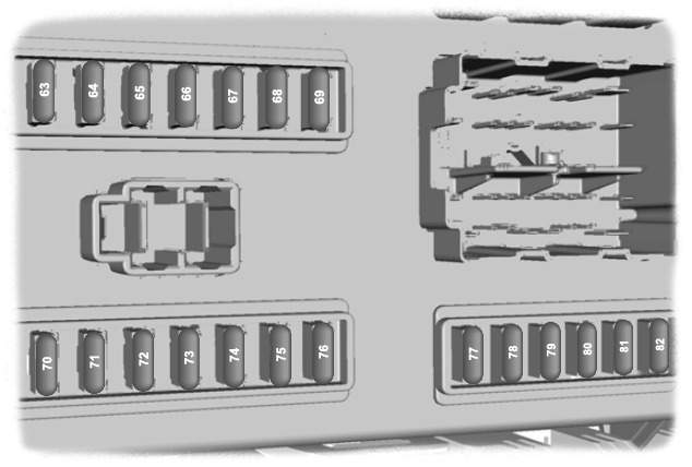
Passenger Junction Box
Ford Transit (2006 to 2010, 2012 to 2013)
| Fuse | Ampere rating | Colour | Circuits protected |
| 63 | 5 | tan | Rear parking aid, rain sensor |
| 64 | 2 | grey | Acceleration pedal demand sensor |
| 65 | 15 | blue | Brake lamp switch |
| 66 | 5 | tan | Instrument cluster, PATS supply, tacho- graph, instrument panel switch illumination |
| 67 | 15 | blue | Washer pump |
| 68 | 10 | red | Restraints control module |
| 69 | 20 | yellow | Exterior lamp switch (KL15) |
| 70 | 20 | yellow | Battery backed sounder |
| 71 | 5 | tan | Exterior lamp switch (KL30) |
| 72 | 10 | red | Battery saver supply, OBDII (KL30) |
| 73 | 15 | blue | Radio, navigation unit and phone supply |
| Fuse | Ampere rating | Colour | Circuits protected |
| 74 | 5 | tan | Instrument cluster, fuel-fired booster heater timer, remote keyless entry supply, interior motion sensor (KL30) |
| 75 | 7.5 | brown | Side lamps right-hand side |
| 76 | 7.5 | brown | Side lamps left-hand side |
| 77 | 5 | tan | Ignition switch supply, battery disconnect switch coils supply |
| 78 | 15 | blue | Central locking |
| 79 | 7.5 | brown | Number plate lamp, side markers |
| 80 | 15 | blue | Front fog lamps |
| 81 | 10 | red | Rear fog lamps |
| 82 | 3 | violet | Audio and instrument cluster ignition feed |
Auxiliary fuses
| Fuse | Ampere rating | Colour | Circuits protected | Location |
| 83 | 10 | red | Trailer tow module | Left-hand side foot- well |
Ford Transit 2010, 2013
| Fuse | Ampere rating | Colour | Circuits protected | Location |
| 83 | 10 | red | Trailer tow module | Left-hand side foot- well |
| 84 | 7.5 | brown | DPF glow plug sensing | Below the engine compartment junction box |
Ford Transit (2011)
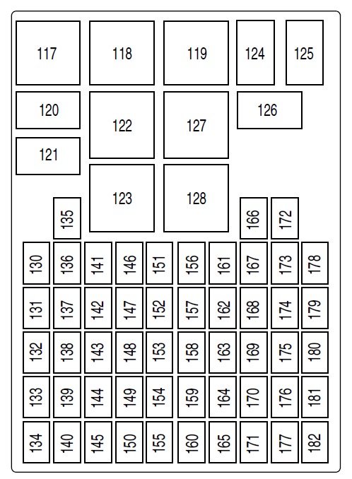
Passenger compartment fuse panel
The fuse panel and relay box are located below the instrument panel to
the left of the steering wheel.
| Fuse/Relay Location | Fuse Amp Rating | Protected Circuits |
| 117 | — | Not used |
| 118 | — | Not used |
| 119 | — | Not used |
| 120 | — | Headlamps, Low beam interrupt relay |
| 121 | — | Front fog lamp interrupt relay |
| 122 | — | Rear window defroster relay |
| 123 | — | Heater blower relay |
| 124 | — | Interior lamps relay |
| 125 | — | Windshield wipers relay |
| Fuse/Relay Location | Fuse Amp Rating | Protected Circuits |
| 126 | — | Rear unlock relay |
| 127 | — | Ignition overload relay |
| 128 | — | Battery saver relay (modified vehicle) |
| 130 | 15A | Hazard flashers |
| 131 | 5A | Power mirrors |
| 132 | 10A | Light switch, Exterior lighting |
| 133 | — | Not used |
| 134 | — | Not used |
| 135 | — | Not used |
| 136 | 15A | Horn |
| 137 | 7.5A | Tire pressure monitoring system (TPMS), Radio, Instrument cluster |
| 138 | 10A | Reverse lamp |
| 139 | 20A | Ignition supply (modified vehicle) |
| 140 | — | Not used |
| 141 | 7.5A | Front/rear fog lamps |
| 142 | 15A | Brake lamps |
| 143 | 20A | Cigar lighter, Front power point |
| 144 | 10A | Ignition supply (modified vehicle) |
| 145 | — | Not used |
| 146 | 20A | Windshield wipers, Wiper switch |
| 147 | 15A | Front fog lamps |
| 148 | 7.5A | Recirculation, Instrument cluster |
| 149 | 10A | Ignition supply/Battery supply (modified vehicle) |
| 150 | — | Not used |
| 151 | 15A | Radio, Bluetooth®/Voice command module |
| 152 | 7.5A | A/C switch, Park aid module |
| 153 | 7.5A | Interior lamps, Battery saver |
| Fuse/Relay Location | Fuse Amp Rating | Protected Circuits |
| 154 | 15A | Roof lamp (modified vehicle) |
| 155 | 10A | Battery saver (modified vehicle) |
| 156 | 7.5A | Right parking lamp/tail lamps |
| 157 | 7.5A | License plate lamps |
| 158 | 10A | Light switch |
| 159 | 20A | Rear heater blower fan (modified vehicle) |
| 160 | — | Not used |
| 161 | 7.5A | Anti-lock brake system (ABS)/RSC, Steering angle sensor |
| 162 | 7.5A | Airbag module, Passenger airbag off indicator |
| 163 | 20A | Locks |
| 164 | 20A | TPMS module |
| 165 | — | Not used |
| 166 | 25A | Front power windows |
| 167 | 7.5A | Rear window defroster/heated mirror switch |
| 168 | — | Not used |
| 169 | 20A | Second power point |
| 170 | — | Not used |
| 171 | — | Not used |
| 172 | 10A | Right rear turn signal (modified vehicle) |
| 173 | 10A | Left rear turn signal (modified vehicle) |
| 174 | 20A | Rear power point, Rear center console power point (modified vehicle) |
| 175 | 7.5A | Left park lamps/tail lamps |
| 176 | — | Not used |
| 177 | — | Not used |
| Fuse/Relay Location | Fuse Amp Rating | Protected Circuits |
| 178 | 25A | Rear window defroster |
| 179 | 7.5A | Instrument cluster, Passive anti-theft system (PATS), Accelerator pedal sensor, TPMS, Rearview camera |
| 180 | 20A | Front and rear window washer |
| 181 | — | Not used |
| 182 | — | Not used |
Engine Junction Box Diagram
Ford Transit (2006 to 2010, 2012 to 2013)
| Fuse | Ampere rating | Colour | Circuits protected |
| 11 | 60 | yellow | Engine cooling fan |
| 12 | 30 | pink | Trailer tow and trailer tow module power supply (KL30) |
| 13 | 40 | green | ABS and ESP pump |
| 14 | – | – | Not used |
| 15 | 60 | yellow | Glow plugs |
| 16 | 60 | yellow | Ignition relay (KL15 #3 |
| 17 | 30 | pink | Starter enable |
| 18 | 40 | green | Ignition feed (KL15) to Passenger junc- tion box |
| 19 | – | – | Not used |
| 20 | 10 | red | ABS, ESP, steering angle sensor, YAW sensor supply (KL30) |
| 21 | 25 | natural | ABS and ESP valves and control unit |
| 22 | 20 | yellow | PCM power relay |
| 23 | – | – | Not used |
| 24 Diesel | 20 | yellow | Additional heater, programmable fuel- fired booster heater |
| 24 Petrol | 20 | yellow | Fuel pump |
| 25 | 5 | tan | Battery-fed relay coils |
| 26 | 15 | blue | PCM Power |
| 27 | 7.5 | brown | Glow plug monit- oring |
| 28 Diesel | 5 | tan | T-MAF sensor |
| Fuse | Ampere rating | Colour | Circuits protected |
| 28 Petrol | 15 | blue | Catalyst monitoring system and HEGO sensors |
| 29 | 5 | tan | Water in fuel sensor (Diesel only), power supply relay coils |
| 30 | 10 | red | Sonic purge valve, injector valves (Petrol only) |
| 31 | 5 | tan | Vehicle speed sensor |
| 32 Diesel | 20 | yellow | Vaporiser glow plug |
| 32 Petrol | 20 | yellow | Coil on plug ignition module |
| 33 | 10 | red | Reversing lamps |
| 34 | 20 | yellow | Trailer tow power supply (KL15) |
| 35 | 5 | tan | Additional heater (KL15) |
| 36 | 10 | red | Air conditioning clutch |
| 37 | 5 | tan | Ignition-fed relay coils, PCM ignition run key sense |
| Relay | Circuits switched |
| R2 | Glow plugs |
| R3 | Not used |
| R4 | Starter enable |
| R5 | Power feed (KL15 #4) |
| R6 | Power feed (KL15 #3) |
| R7 Diesel | Vaporiser glow plug |
| Relay | Circuits switched |
| R7 Petrol | Fuel pump |
| R8 | Powertrain control module power |
| R9 | Not used |
| R10 | Air conditioning clutch solenoid |
Ford Transit (2011)
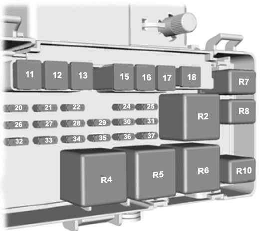
| Fuse/Relay Location | Fuse Amp Rating | Protected circuits |
| 1 | 7.5A* | Heated windshield telltale |
| 2 | 40A** | Right heated windshield, Modified vehicle — Rear heater blower fan, Ignition supply |
| 3 | 50A** | Left heated windshield, Modified vehicle — Battery supply |
| 4 | 20A** | Fuel pump |
| 5 | 10A* | Powertrain control module (PCM) keep alive power, Canister solenoid |
| 6 | 15A* | PCM, Data link connector |
| 7 | 20A* | Ignition switch |
| 8 | 15A* | Headlamps |
| 9 | 40A** | Passenger compartment fuse panel II |
| 10 | 25A** | Rear turn signal, Modified vehicle — Battery supply |
| 11 | 40A** | Ignition overload, Passenger compartment fuse panel |
| 12 | 30A** | Anti-lock brake system (ABS)/Roll stability control (RSC) pump motor |
| Fuse/Relay Location | Fuse Amp Rating | Protected circuits |
| 13 | 30A* | Heater blower motor |
| 14 | 10A* | PCM relay |
| 15 | 20A** | ABS/RSC valves |
| 16 | 30A** | Cooling fan – low |
| 17 | 50A** | Cooling fan – high |
| 18 | 25A** | Daytime running lamps (DRL), Low beam interrupt relay |
| 19 | 50A** | Passenger compartment fuse panel III |
| 20 | — | A/C clutch relay |
| 21A | — | Right heated windshield relay, Modified vehicle — Rear fan relay |
| 21B | — | Starter lock relay |
| 21C | — | High beam headlamp relay |
| 21D | — | PCM relay |
| 22 | 10A* | PCM, Auxiliary connector, Fuel injectors |
| 23 | 10A* | Right low beam headlamp |
| 24 | 10A* | A/C clutch solenoid |
| 25 | 10A* | Left low beam headlamp |
| 26 | 10A* | Mass air flow sensor, Brake switch, Backup lamps relay, EGR stepper motor, EVAP canister purge valve, Heated oxygen sensors, Floor shifter, Transmission range sensor |
| 27 | — | Not used |
| 28 | 15A* | PCM vehicle power 1 |
| 29 | 15A* | Auxiliary connector, Coil on plugs |
| 30A | 70A Relay | Cooling fan high relay |
| 30B | ||
| 30C | — | Cooling fan low relay |
| Fuse/Relay Location | Fuse Amp Rating | Protected circuits |
| 30D | — | Left heated windshield relay |
| 31A | — | Backup lamp relay |
| 31B | — | Fuel pump relay |
| 31C | — | DRL relay |
| 31D | — | Low beam headlamps relay |
| 31E | — | Modified vehicle — Right rear turn signal relay |
| 31F | — | Front fog lamps |
| 32 | — | Cooling fan diode |
| 33 | — | Fuel pump relay diode |
| 34 | — | Gear shifter diode |
| 35 | 30A* | Start lock relay |
| 36 | — | Modified vehicle — Left rear turn signal relay |
| *Mini fuse **Cartridge fuse | ||