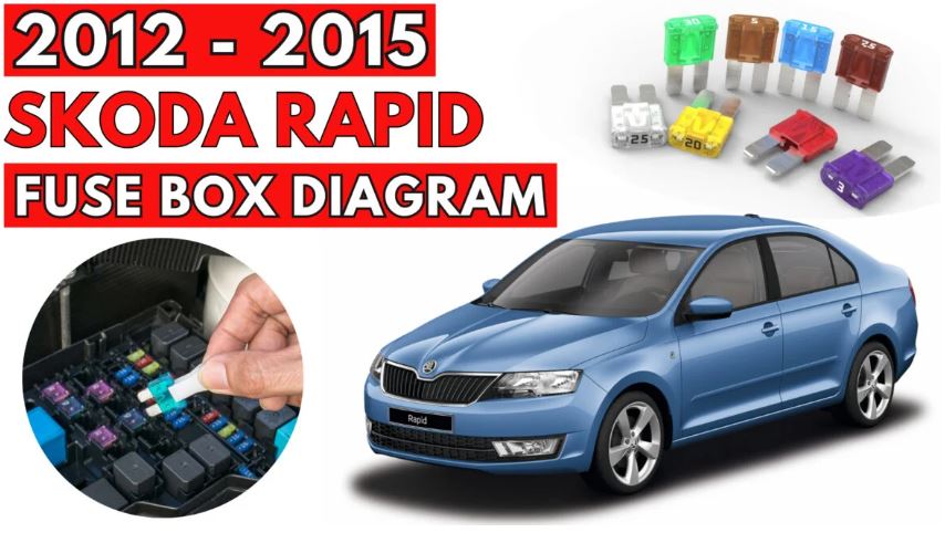
Skoda Rapid (2012 – 2015) Fuse Box Location and Diagrams
Fuse box diagrams and locations for the Skoda Rapid (2012–2015) are covered in this blog. Understand fuse layouts to diagnose electrical faults and maintain vehicle safety and functionality. The compact sedan of this generation is practical and reliable.
Fuses in the dash panel
Skoda Rapid (2012 to 2015)
Fuse box location
The fuse box is located behind a cover below the steering wheel.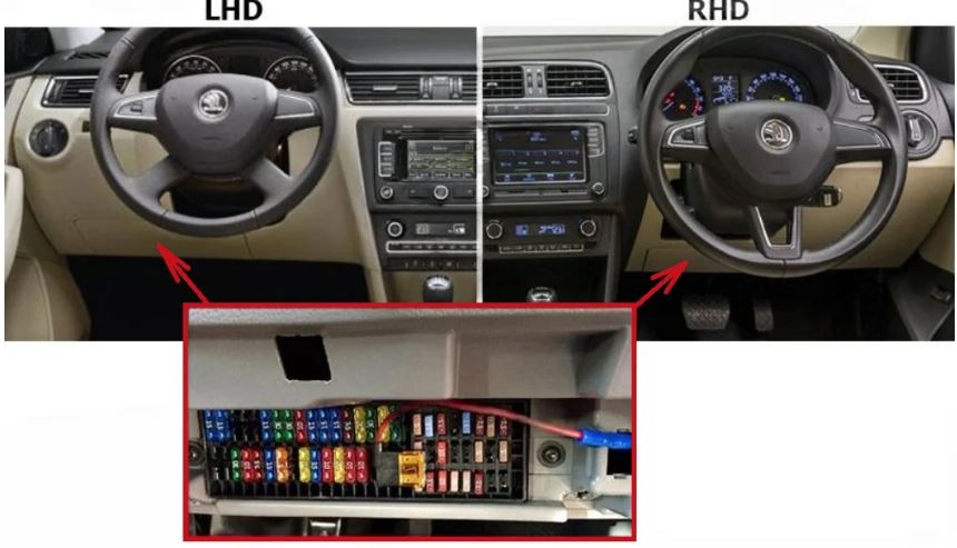
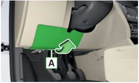
Fuse box diagram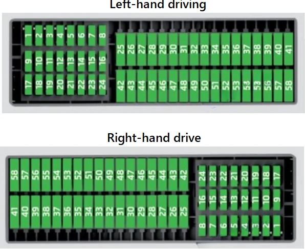
| No. | Power consumer |
|---|---|
| 1 | S-contact |
| 2 | START – STOP |
| 3 | Instrument cluster, headlight range adjustment, telephone, oil level sensor, diagnostic port, dimmable interior rear-view mirror |
| 4 | Control unit for ABS/ESC, steering angle sensor strip with switches |
| 5 | Petrol engine: Speed regulating system |
| 6 | Reversing light (manual gearbox) |
| 7 | Ignition, engine control unit, automatic gearbox |
| 8 | Brake pedal switch, clutch switch, engine cooling fan |
| 9 | Operating controls for the heating, electronic control unit for air conditioning system, park distance control, window lift, engine cooling fan, heated washer nozzles |
| 10 | DC-DC converter |
| 11 | Mirror adjustment |
| 12 | Control unit for trailer detection |
| 13 | Electronic control unit for automatic gearbox, selector lever of the automatic gearbox |
| 14 | Headlight range control |
| 15 | Not assigned |
| 16 | Power steering, speed sensor, engine control unit, control unit for fuel pump |
| 17 | Daytime running lights/radio for vehicles with START-STOP |
| 18 | Mirror heater |
| 19 | Ignition lock input |
| 20 | Engine control unit, electronic control unit for fuel pump, fuel pump |
| 21 | Reversing lamp (automatic gearbox), fog lights with the function CORNER |
| 22 | Operating controls for the heating, electronic control unit for air conditioning system, telephone, instrument cluster, steering angle sender, multi-function steering wheel, ignition key removal lock, diagnostic port, rain sensor |
| 23 | Interior lighting, storage compartment and luggage compartment, side lights |
| 24 | Central control unit |
| 25 | Light switch |
| 26 | Rear window wiper |
| 27 | Not assigned / Operating lever underneath the steering wheel |
| 28 | Petrol engine: Purge valve, PTC heater |
| 29 | Injection, coolant pump |
| 30 | Fuel pump, ignition system, cruise control |
| 31 | Lambda probe |
| 32 | High-pressure fuel pump, control valve for fuel pressure |
| 33 | Engine control unit |
| 34 | Engine control unit, vacuum pump |
| 35 | Switch illumination, number plate light, parking light |
| 36 | High beam, light switch |
| 37 | Rear fog light, DC-DC converter |
| 38 | Fog lights |
| 39 | Air blower for heating |
| 40 | Not assigned |
| 41 | Heated front seats |
| 42 | Rear window heater |
| 43 | Horn |
| 44 | Windscreen wipers |
| 45 | Boot lid lock, central locking system |
| 46 | Alarm |
| 47 | Cigarette lighter |
| 48 | ABS |
| 49 | Turn signal lights, brake lights |
| 50 | DC-DC converter, radio |
| 51 | Electric windows (driver’s window and rear left window) |
| 52 | Electric windows (front passenger’s window and rear right) |
| 53 | Windscreen washer |
| 54 | START-STOP instrument cluster, operating lever under the steering wheel, multifunction steering wheel |
| 55 | Control unit for automatic gearbox |
| 56 | Headlight cleaning system |
| 57 | Headlights front, rear |
| 58 | Headlights front, rear |
Fuses in the engine compartment
Skoda Rapid (2012 to 2015)
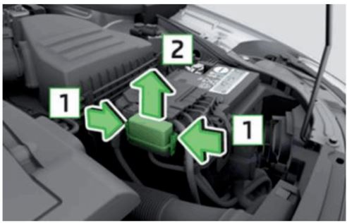
Fuse box location
- Fuse box diagram (version 1)

- Fuse box diagram (version 2)

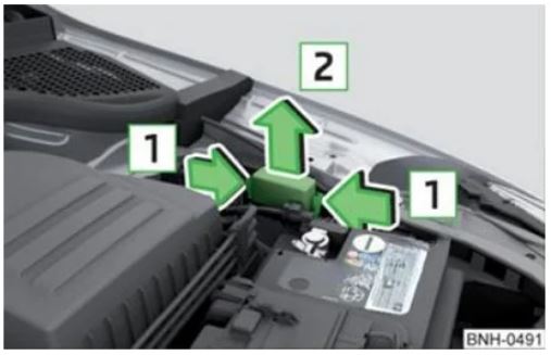
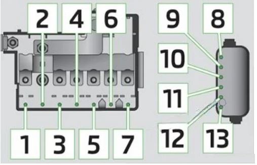
Fuse box diagram (version 1)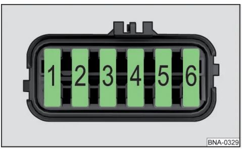
| No. | Power consumer |
|---|---|
| 1 | Generator |
| 2 | Not assigned |
| 3 | Interior |
| 4 | Auxiliary electric heating |
| 5 | Interior |
| 6 | Engine cooling fan, control unit for preheating unit |
| 7 | Electrohydraulic power steering |
| 8 | ABS |
| 9 | Radiator fan |
| 10 | Automatic gearbox |
| 11 | ABS |
| 12 | Central control unit |
| 13 | Electrical auxiliary heating system |
Fuse box diagram (version 2)
| No. | Power consumer |
|---|---|
| 1 | Generator |
| 2 | Auxiliary electric heater |
| 3 | Power supply for fuse block |
| 4 | Interior |
| 5 | Interior |
| 6 | Engine cooling fan, control unit for preheating unit |
| 7 | Electrohydraulic power steering |
| 8 | ABS |
| 9 | Radiator fan |
| 10 | Automatic gearbox |
| 11 | ABS |
| 12 | Central control unit |
| 13 | Electrical auxiliary heating system |
Fuse box diagram (version 3)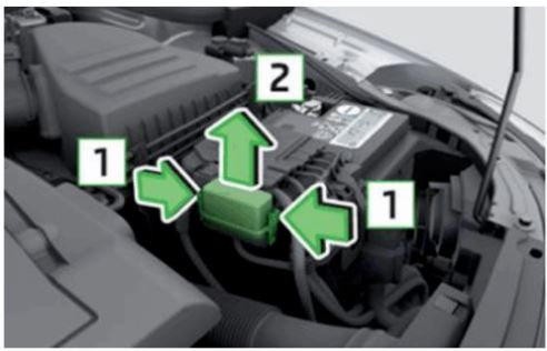
| No. | Power consumer |
|---|---|
| 1 | ABS |
| 2 | Radiator fan |
| 3 | Automatic gearbox |
| 4 | ABS |
| 5 | Central control unit |
| 6 | Electrical auxiliary heating system |