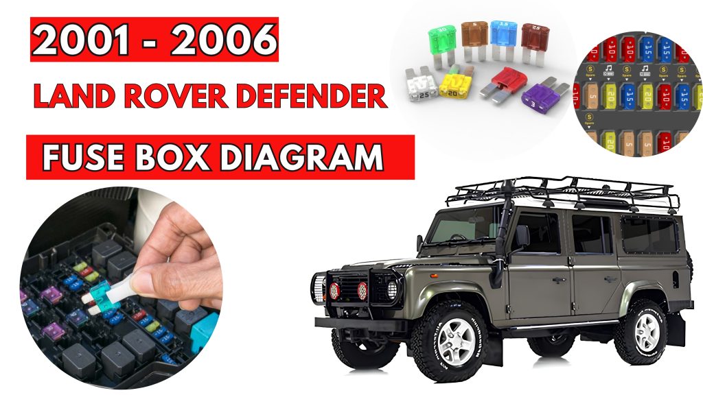
Land Rover Defender (2001 – 2006) Fuse Box Location & Diagrams
The Land Rover Defender (2001–2006) fuse box protects essential electrical systems throughout the vehicle. Knowing its location and fuse diagram helps identify the correct fuse for lighting, accessories, engine controls, and other electrical components when diagnosing common electrical problems.
Fuse Box Location
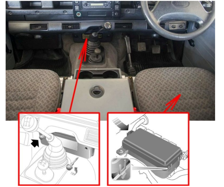
Passenger Compartment Fuse Box
- The main fuse box is fitted in the centre of the dashboard, in front of the main gear lever; to access the fuses, remove the cover by turning the fixing screws fully anti-clockwise.
- The secondary fuse box is located under the right hand front seat. The front seat cushions can be removed to access the battery and secondary fuse box as follows: Pull up the front of the seat base to release it from its retaining clips, then pull the cushion forward to remove.
Fuse Box Diagrams
Passenger Compartment Fuse Box
Main fuse box diagram
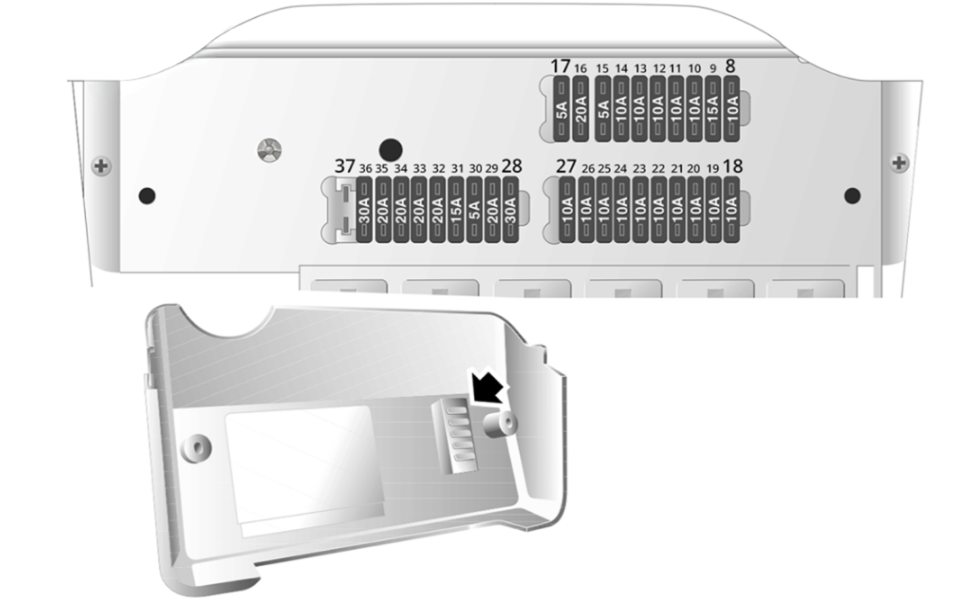
| № | Amps | Circuit protected |
|---|---|---|
| 8 | 10A | Alarm system, ignition |
| 9 | 15A | Wipers & washers – front |
| 10 | 10A | Wipers & washers – rear |
| 11 | 10A | Anti-lock brakes |
| 12 | 10A | Engine ECU (Td5 engine) |
| 13 | 10A | Brake lights |
| 14 | 10A | Reversing lights, glow plugs |
| 15 | 5A | Headlights (dim dip), ignition, air conditioning, cooling fan, instruments, heated rear window, warning lights |
| 16 | 20A | Cigar lighter, heater blower |
| 17 | 5A | Radio |
| 18 | 10A | Side lights (left-hand side), instrument illumination |
| 19 | 10A | Side lights (right-hand side) |
| 20 | 10A | Switch illumination, headlight levelling |
| 21 | 10A | Indicators |
| 22 | 10A | Headlight dipped beam (right-hand side) |
| 23 | 10A | Headlight dipped beam (left-hand side) |
| 24 | 10A | Headlight main beam (right-hand side) |
| 25 | 10A | Headlight main beam (left-hand side) |
| 26 | 10A | Rear fog guard light |
| 27 | 10A | Alarm sounder |
| 28 | 30A | Air conditioning blower |
| 29 | 20A | Air conditioning compressor, cooling fan |
| 30 | 10A | Interior lights, instruments, radio, diagnostic connector |
| 31 | 15A | Hazard warning lights |
| 32 | 20A | Heated rear window |
| 33 | 20A | Heated seats |
| 34 | 20A | Electric window (right-hand side) |
| 35 | 20A | Electric window (left-hand side) |
| 36 | 30A | Heated front screen |
| 37 | – | – |
Secondary fuse box diagram
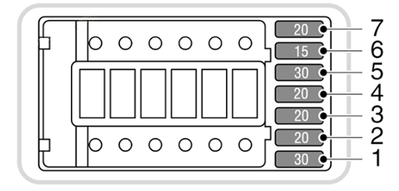
| № | Amps | Circuit protected |
|---|---|---|
| 1 | 30A | ABS |
| 2 | 20A | Accessory socket, trailer |
| 3 | 20A | Horn |
| 4 | 20A | Fuel pump |
| 5 | 30A | Main relay |
| 6 | 15A | Alarm, hazards |
| 7 | 20A | Alarm sounder, CDL |
| 100A | GLOW PLUG | |
| 60A | AIR CON | |
| 60A | SPARE | |
| 30A | ABS PUMP RELAY | |
| 60A | IGNITION | |
| 30A | LIGHTS |
NOTE: On TD5 models, an additional fuse is taped to the wiring harness alongside the secondary fuse box. This fuse protects the engine management sensors.
RELATED POSTS: