
Mahindra Bolero Neo (2021 – 2023) Fuse Box Location & Diagrams
The Mahindra Bolero Neo (2021 – 2023) features multiple fuse boxes that protect essential electrical systems. This blog covers the fuse box locations and diagrams, helping you identify fuse positions, functions, and electrical circuits for easier troubleshooting and maintenance.
Fuse Box Location
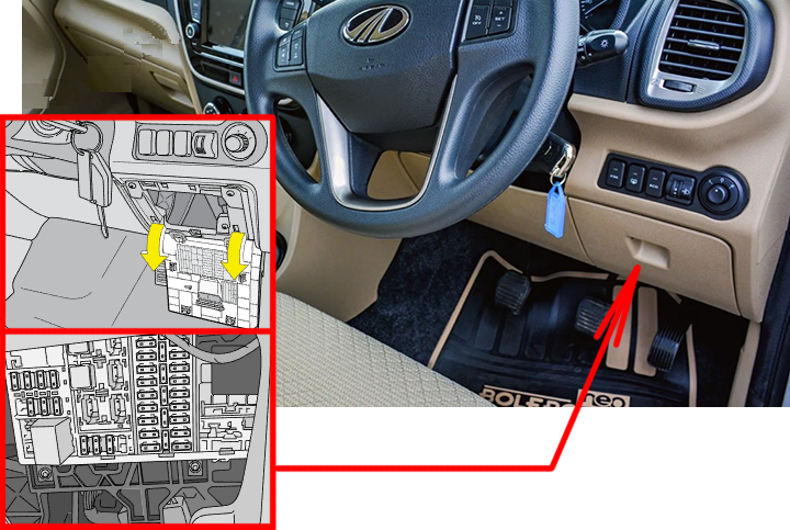
Passenger Compartment Fuse Box
Pull the fuse box cover below the switch bank outward to access the instrument panel fuse box. Spare fuses are available in this fuse box location.
Engine Compartment Fuse Box
The engine compartment fuse box is located adjacent to the vehicle’s battery. A fuse puller is available in this fuse box location.
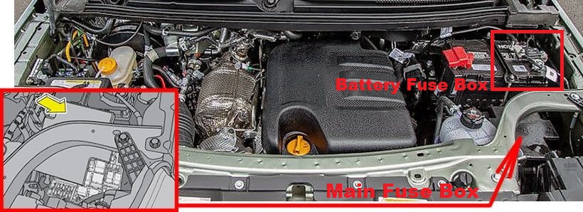
Follow the steps below to remove the fuse cover:
- Slightly press/nudge the fuse cover towards the headlamp side and remove the front snap lock;
- Further, push the top cover towards the battery side and remove/pull the cover completely.
Fuse Box Diagrams
Passenger Compartment Fuse Box
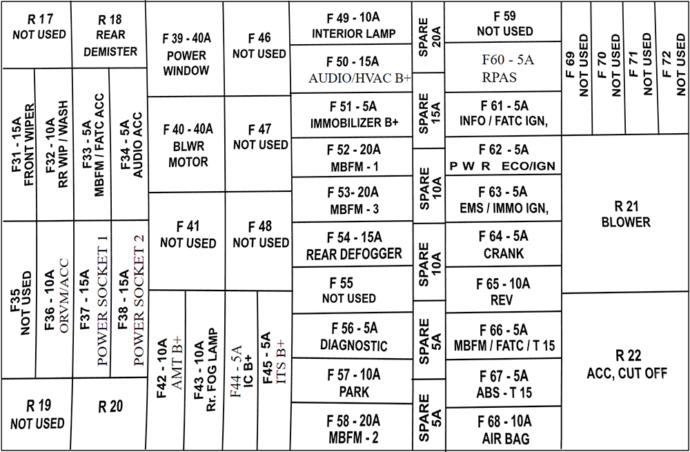
| № | Amps | Circuit |
|---|---|---|
| F31 | 15A | Front Wiper |
| F32 | 10A | Rear Wiper / Wash Infotainment / IC |
| F33 | 5A | MBFM/ACC |
| F34 | 5A | Audio ACC |
| F35 | – | – |
| F36 | 10A | ORVM/ACC |
| F37 | 15A | Power Socket 1 |
| F38 | 15A | Power Socket 2 |
| F39 | 40A | Power window |
| F40 | 40A | Blower motor |
| F41 | – | – |
| F42 | 10A | AMT B+ |
| F43 | 10A | Rear fog lamp |
| F44 | 5A | Instrument cluster B+ |
| F45 | 5A | ITS B+ |
| F46 | – | – |
| F47 | – | – |
| F48 | – | – |
| F49 | 10A | Interior lamp |
| F50 | 15A | AUDIO / HVAC B+ |
| F51 | 5A | Immobilizer B+ |
| F52 | 20A | MBFM-1 |
| F53 | 20A | MBFM-3 |
| F54 | 15A | Rear Defogger |
| F55 | – | – |
| F56 | 5A | Diagnostics |
| F57 | 10A | Park lamp |
| F58 | 20A | MBFM-2 |
| F59 | – | – |
| F60 | 5A | RPAS |
| F61 | 5A | Infotainment/ FATC IGN |
| F62 | 5A | Power ECO/IGN |
| F63 | 5A | EMS/ Immo IGN |
| F64 | 5A | Crank |
| F65 | 10A | Reverse |
| F66 | 5A | MBFM / FATC / T15 |
| F67 | 5A | ABS – T15 |
| F68 | 10A | Airbag |
| F69 | – | – |
| F70 | – | – |
| F71 | – | – |
| F72 | – | – |
| Relays | ||
| R15 | – | |
| R18 | De-mister Relay | |
| R19 | – | |
| R20 | – | |
| R21 | Blower | |
| R22 | AC cut off |
Engine Compartment Fuse Box
Main Fuse Box
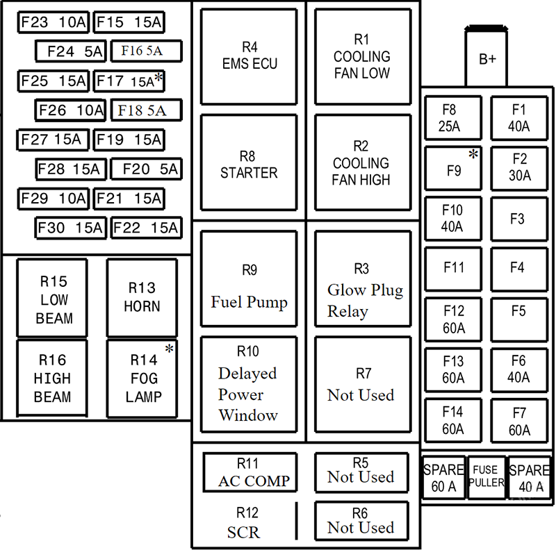
| № | Amps | Circuit |
|---|---|---|
| F1 | 40A | ABS Motor |
| F2 | 30A | EMS Loads |
| F3 | – | – |
| F4 | – | – |
| F5 | – | – |
| F6 | 40A | Starter solenoid |
| F7 | 60A | EC Mini Fuse B+ |
| F8 | 25A | ABS Solenoid |
| F9 | 40A | Glow plug |
| F10 | 40A | Extended Power Window |
| F11 | – | – |
| F12 | 60A | Battery Cable 2 |
| F13 | 60A | Battery Cable 1 |
| F14 | 60A | Battery Cable 3 |
| F15 | 15A | Horn |
| F16 | 5A | DRL |
| F17 | 15A | Front fog lamp |
| F18 | 5A | SCR |
| F19 | 15A | Low beam |
| F20 | 5A | BMS, EMS |
| F21 | 15A | High beam |
| F22 | 15A | Fuel Pump |
| F23 | 10A | Relay Coil |
| F24 | 5A | ESS/ WIF/ TPS |
| F25 | 15A | EGR/ PBA/ FMU |
| F26 | 10A | AC Compressor |
| F27 | 15A | EMS Battery 2 |
| F28 | 15A | NoX, HFM, UDM |
| F29 | 10A | EMS Battery 1 |
| F30 | 15A | Brake switch |
| Relays | ||
| R1 | Cooling Fan Low | |
| R2 | Cooling Fan High | |
| R3 | Glow Plug | |
| R4 | EMS ECU | |
| R5 | – | |
| R6 | – | |
| R7 | – | |
| R8 | Starter Relay | |
| R9 | Fuel Pump | |
| R10 | Extended Power Window | |
| R11 | AC Compressor | |
| R12 | SCR | |
| R13 | HORN | |
| R14 | Fog Lamp | |
| R15 | Low Beam | |
| R16 | High Beam |
Auxiliary Fuse Box
The battery-mounted fuse box is connected to the positive terminal of the battery.
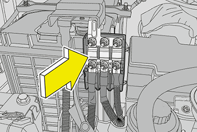
| Circuit | Amps | Colour |
|---|---|---|
| Main charging fuse | 125A | Pink colour |
| Bus bar fuse | 80A | White colour |
| Cooling fan fuse | 60A | Yellow colour |
Related Posts: