

Mahindra NuvoSport (2016 – 2020) Fuse Box Location & Diagrams
The Mahindra NuvoSport (2016 – 2020) features accessible fuse boxes that protect essential electrical systems and components. This blog covers the fuse box locations and diagrams, helping you identify fuse positions and understand their functions when checking or replacing fuses.
Fuse Box Location
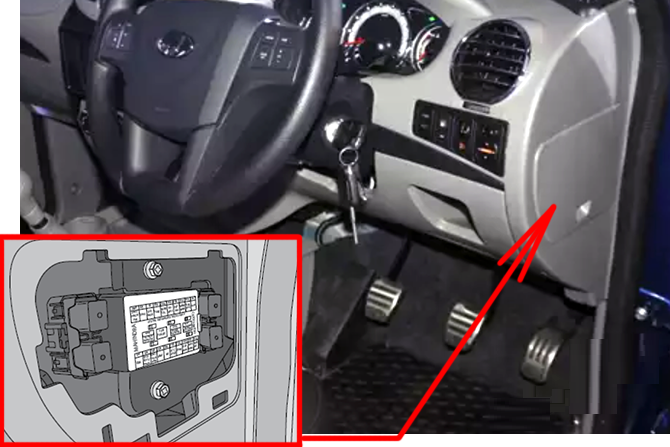
Passenger Compartment Fuse Box
Pull the Fuse box cover below the switch bank outward to access the instrument panel fuse box.
Engine Compartment Fuse Box
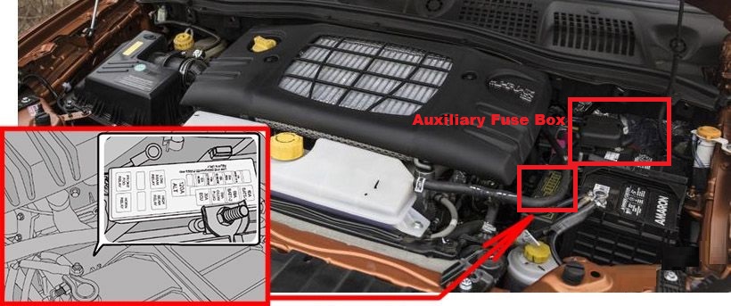
The engine compartment fuse box is located adjacent to the vehicle battery. Slightly press/nudge the fuse cover towards the headlamp side and remove the front snap lock. Further, push the top cover towards the battery side and remove/pull the cover completely.
Fuse Box Diagrams
Passenger Compartment Fuse Box
Main Fuse Box
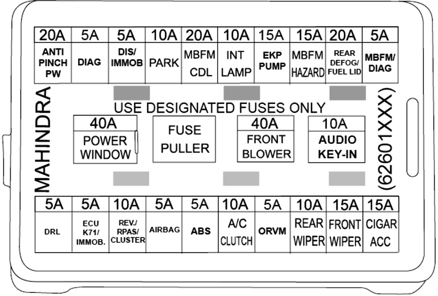
| № | Amps | Circuit |
|---|---|---|
| 1 | 20A | ANTI PINCH PW |
| 2 | 10A | TCU B+ |
| 3 | 5A | DIS / IMMO |
| 4 | 10A | PARK |
| 5 | 20A | MBFM / CDL |
| 6 | 10A | INT LMP |
| 7 | 15A | EKP PUMP |
| 8 | 10A | Park |
| 9 | 15A | MBFM / HAZARD |
| 10 | 20A | REAR DEFOG / FUEL LID |
| 11 | 15A | MBFM / DIAG |
| 12 | 5A | DRL |
| 13 | 5A | ECU K-71 / IMMO |
| 14 | 10A | REV / RPAS / CLUSTER / ORVM |
| 15 | 5A | AIRBAG |
| 16 | 5A | ABS |
| 17 | 5A | TCU / TGS |
| 18 | 10A | AC CLUTCH |
| 19 | 10A | REAR WIPER |
| 20 | 15A | FRONT WIPER |
| 21 | 15A | CIGAR / ACC |
| 22 | 10A | AUDIO KEY IN |
| 23 | 40A | POWER WINDOW |
| 24 | 40A | FRONT BLOWER |
| 25 | 40A | PUMP MOTOR |
Auxiliary Fuse Box
The engine wiring harness fuse box is located below the IP.
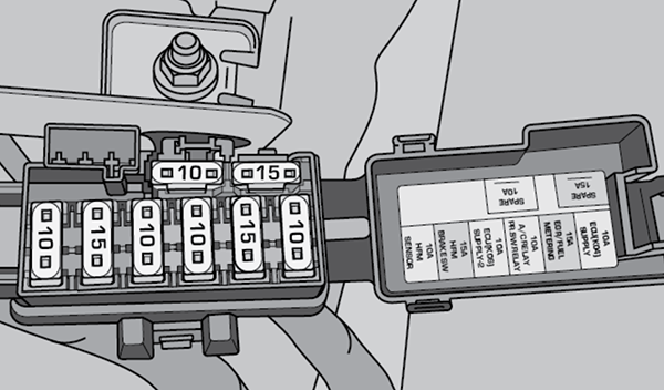
| № | Amps | Circuit |
|---|---|---|
| 1 | 15A | EGR / FUEL METERING |
| 2 | 15A | BRAKE CLUTCH |
| 3 | 10A | ECU K-6 |
| 4 | 10A | ECU-K4 |
| 5 | 10A | AC RELAY / PR.SW RELAY |
| 6 | 10A | HFM SENSOR |
Relays
| № | Circuit |
|---|---|
| 1 | Blower Fan Relay |
| 2 | Pressure Sw.Relay |
| 3 | Pump Motor Relay |
| 4 | AC comp.Relay |
| 5 | Fuel Pump Relay |
| 6 | Inter. Fog Relay |
| 7 | Demister Relay |
| 8 | High beam Relay |
| 9 | Low Beam Relay |
| 10 | Horn Relay |
| 11 | Front Fog Relay |
| 12 | Starter Relay |
| 13 | Cooling Fan Relay -1 |
| 14 | Cooling Fan Relay -2 |
| 15 | Glow Plug Relay |
| 16 | ECU relay |
| 17 | Changeover relay |
Engine Compartment Fuse Box
Main Fuse Box
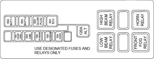
| № | Amps | Circuit |
|---|---|---|
| 1 | 120A | Alternator |
| 2 | 60A | BATT-1 |
| 3 | 60A | BATT-2 |
| 4 | 60A | GLOW PLUG |
| 5 | 30A | ECU |
| 6 | 15A | FRONT FOG |
| 7 | 15A | HI BEAM |
| 8 | 15A | LOW BEAM |
| 9 | 15A | HORN |
| 10 | 25A | ABS |
Auxiliary Fuse Box
The battery-mounted fuse box is connected to the battery’s positive terminal. The functionality of the battery-mounted fuse box is to provide short-circuit protection to the alternator, power supply to the main engine compartment fuse box & electric cooling fan.
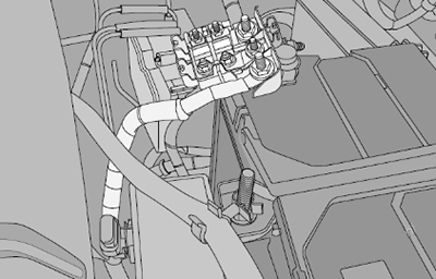
| № | Amps | Circuit |
|---|---|---|
| 1 | 60A | Cooling Fan -1 |
| 2 | 60A | Cooling Fan -1 |
Related Posts: