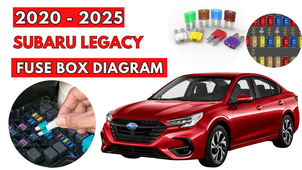
Subaru Legacy (2020 – 2025) Fuse Box Location & Diagrams
The Subaru Legacy (2020–2025) features multiple fuse boxes that protect important electrical systems and components. Knowing their locations and fuse assignments makes it easier to identify electrical issues, replace blown fuses, and maintain your vehicle. This resource provides clear fuse box locations, diagrams, fuse ratings, and component descriptions.
Fuse Box Location
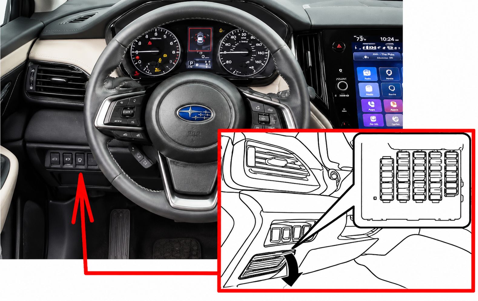
Passenger Compartment Fuse Box
It is located behind the cover below and to the left of the steering wheel.
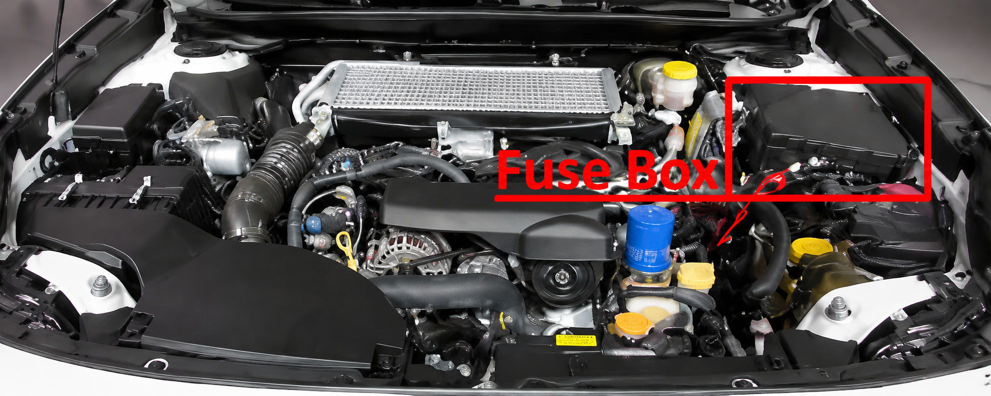
Engine Compartment Fuse Box
Fuse Box Diagrams
Passenger Compartment Fuse Box
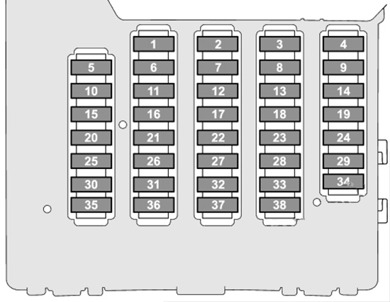
| № | Amps | Name | Description |
|---|---|---|---|
| 1 | – | – | – |
| 2 | 20 A | CIGAR | Cigar lighter / power outlet |
| 3 | 7.5 A | IG A-1 | IG A-1 |
| 4 | 15 A | AUDIO NAVI | Audio system |
| 5 | 10 A | IG B-2 | IG B-2 |
| 6 | 7.5 A | METER IG (DCDC) | Instrument cluster |
| 7 | 20 A | 12V SOCKET | Cigar lighter / power outlet |
| 8 | 10 A | A/C IG | Air conditioning |
| 9 | 7.5 A | ACC | ACC |
| 10 | 7.5 A | IG B-1 | IG B-1 |
| 11 | 7.5 A | EYE SIGHT (DCDC) | EyeSight Driver Assist Technology |
| 12 | – | – | – |
| 13 | 7.5 A | IG A-3 | IG A-3 |
| 14 | – | – | – |
| 15 | – | – | – |
| 16 | 7.5 A | UNIT IG (DCDC) | UNIT IG (DCDC) |
| 17 | 7.5 A | MIRROR ACC | Power control mirror |
| 18 | – | – | – |
| 19 | 10 A | IG A-2 | IG A-2 |
| 20 | 10 A | SRS AIRBAG | Airbag |
| 21 | 7.5 A | A/C IG (DCDC) | Air conditioning |
| 22 | 10 A | EYE SIGHT | EyeSight Driver Assist Technology |
| 23 | 7.5 A | IGA-4 | IGA-4 |
| 24 | 7.5 A | A/C ACC (DCDC) | Air conditioning |
| 25 | 7.5 A | UNIT +B (DCDC) | UNIT +B (DCDC) |
| 26 | 10 A | BACK UP | Backup lights |
| 27 | 15 A | SEAT HTR R | Rear seat heater |
| 28 | 20 A | TRAIL R.FOG | Trailer fog lights |
| 29 | – | – | – |
| 30 | 7.5 A | BACK UP (DCDC) | Backup lights |
| 31 | 7.5 A | SMT (DCDC) | Smart key system |
| 32 | 15 A | MIRROR +B | Power control mirror |
| 33 | 7.5 A | KEY SW A | Ignition switch |
| 34 | – | – | – |
| 35 | 7.5 A | ILLUMI (DCDC) | Illumination |
| 36 | 7.5 A | KEY SW B | Ignition switch |
| 37 | 15 A | UNIT +B1 | UNIT +B1 |
| 38 | 7.5 A | UNIT +B2 | UNIT +B2 |
Engine Compartment Fuse Box
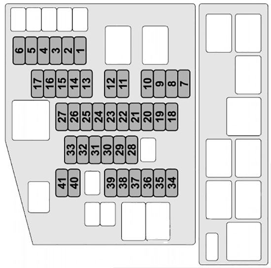
| № | Amps | Name | Description |
|---|---|---|---|
| 1 | – | – | – |
| 2 | 7.5 A | OBD | On-board diagnostics |
| 3 | 7.5 A | STOP | Stop lights |
| 4 | 10 A | MB-B | MB-B |
| 5 | 7.5 A | PU B/UP | Power unit back up |
| 6 | 30 A | JB-B2 | JB-B2 |
| 7 | 7.5 A | M/B-IG1 | M/B-IG1 |
| 8 | 7.5 A | M/B-IG2 | M/B-IG2 |
| 9 | 10 A | M/B-IG3 | M/B-IG3 |
| 10 | 7.5 A | M/B-IG4 | M/B-IG4 |
| 11 | 7.5 A | HORN1 | Horn |
| 12 | 7.5 A | HORN2 | Horn |
| 13 | 10 A | TAIL | Tail lights |
| 14 | 15 A | HAZARD | Hazard light |
| 15 | 20 A | D/L | Power door lock system |
| 16 | 20 A | F/P | Fuel pump |
| 17 | – | – | – |
| 18 | – | – | – |
| 19 | 10 A | AVCS | Engine active valve control system |
| 20 | 15 A | ETC | Electronic throttle control |
| 21 | 15 A | TCU | Transmission control unit |
| 22 | 7.5 A | CVT SSR | CVT Transmission |
| 23 | 10 A | E/G2 | Engine control and emissions control (EGR) |
| 24 | 15 A | IG COIL | Ignition coil |
| 25 | 20 A | O2 HTR | Oxygen sensor |
| 26 | 20 A | DI | Direct ignition |
| 27 | 15 A | E/G1 | Engine control and emissions control (EGR) |
| 28 | 25 A | MAIN FAN | Radiator fan |
| 29 | 15 A | DEICER | Deicer or defroster |
| 30 | 30 A | VDC SOL | Vehicle dynamics control solenoid |
| 31 | 15 A | F-END | F-END |
| 32 | 30 A | F.WIP | Front wipers |
| 33 | 25 A | R.DEF | Rear window defogger |
| 34 | 30 A | BACKUP | Backup lights |
| 35 | 20 A | HTR | Air conditioning system |
| 36 | 25 A | SUB FAN | Cooling fan motor |
| 37 | 15 A | R.WIP | Rear wiper |
| 38 | 20 A | BLOWER | AC blower motor |
| 39 | 20 A | BLOWER | AC blower motor |
| 40 | 10 A | MB-A | MB-A |
| 41 | – | – | – |
Related Posts: