Pontiac GTO (2004 – 2006) Fuse Box Location & Diagrams
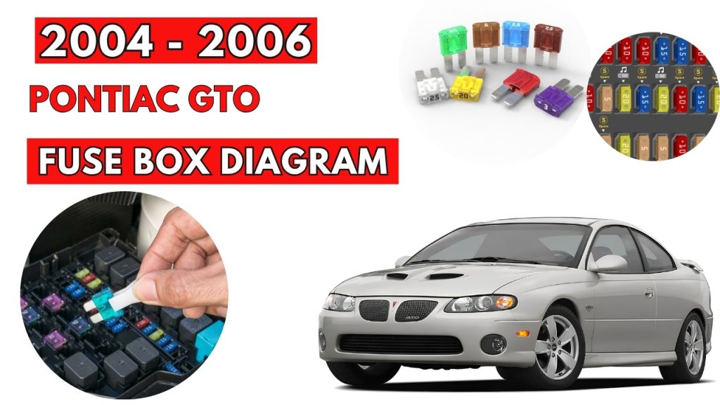
The Pontiac GTO (2004–2006) uses fuse boxes to protect important electrical circuits and components. Knowing the correct fuse locations and assignments makes troubleshooting electrical problems easier. This guide covers fuse box locations, diagrams, fuse ratings, and protected components for the Pontiac GTO.
Fuse Box Location
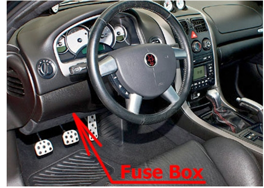
Passenger Compartment Fuse Box
It is located behind the panel below the steering wheel.
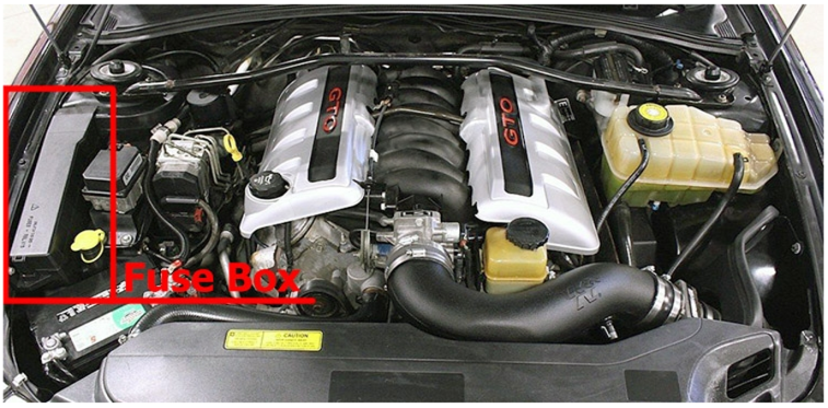
Engine Compartment Fuse Box
Fuse Box Diagram
Passenger Compartment Fuse Box
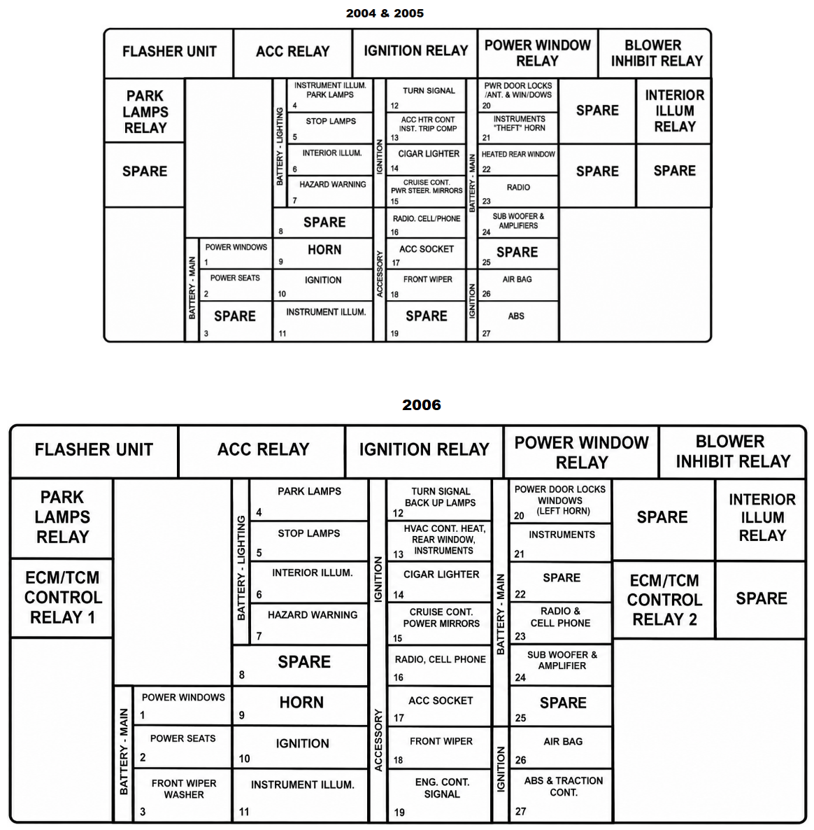
| Name | Description |
|---|---|
| FLASHER UNIT | Hazard Warning Flashers |
| POWER WINDOWS | Power Window Switches |
| POWER SEATS | Power Seat Controls |
| FRONT WIPER WASHER | Front Windshield Wiper Washer |
| PARK LAMPS | Parking Lamps |
| STOP LAMPS | Stop Lamps |
| INTERIOR ILLUM | Interior light Controls |
| HAZARD WARNING | Hazard Warning Flashers |
| SPARE | Spare |
| HORN | Horn |
| IGNITION | Ignition Switch |
| INSTRUMENT ILLUM. | Instrument Panel Lighting |
| TURN SIGNAL,BACK UP LAMPS | Turn Signal Lamp, Back-Up Lamps |
| HVAC CONT. HEAT, REAR WINDOW, INSTRUMENTS | Heater Controls, Rear Window, Trip Computer |
| CIGAR LIGHTER | Cigarette Lighter |
| CRUISE CONT. POWER MIRRORS | Cruise Control, Power Mirror |
| RADIO, CELL PHONE | Radio System, Cell Phone |
| ACC. SOCKET | Accessory Power Outlet |
| ENG. CONT. SIGNAL | Engine Control Signal |
| POWER DOOR LOCKS, WINDOWS & THEFT HORN | Power Door Locks, Power Windows, Theft System, Horn |
| INSTRUMENTS | Instruments |
| RADIO & CELL PHONE | Radio System, Cell Phone |
| SUB WOOFER & AMPLIFIER | Sub Woofer and Amplifier |
| AIRBAG | Airbag |
| ABS & TRACTION CONT | Anti-Lock Brake System, Traction Control System |
| Relays | |
| ACC RELAY | Accessory Power Outlet |
| IGNITION RELAY | Ignition Switch |
| POWER WINDOW RELAY | Power Windows |
| BLOWER INHIBIT RELAY | Blower |
| PARK LAMPS RELAY | Parking Lamps |
| SPARE | Spare |
| INTERIOR ILLUM RELAY | Interior Light Controls |
| ECM/TCM CONTROL RELAY 1 | Engine Control Module, Transmission Control Module 1 |
| ECM/TCM CONTROL RELAY 2 | Engine Control Module, Transmission Control Module 2 |
Engine Compartment Fuse Box
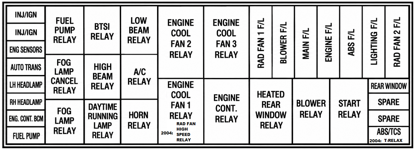
| Name | Description |
|---|---|
| INJ/IGN | Fuel Injectors and Ignition Modules |
| ENG SENSORS | Engine Sensors |
| AUTO TRANS | Automatic Transmission |
| LH HEADLAMP | Left Headlamp |
| RH HEADLAMP | Right Headlamp |
| ENG CONT. BCM | Engine and Body Control Module |
| FUEL PUMP | Fuel Pump |
| RAD FAN 1 F/L | Engine Cooling Fan 1 |
| BLOWER F/L | Blower Fan |
| MAIN F/L | Main Power Supply |
| ENGINE F/L | Engine System |
| ABS F/L | Anti-Lock Brake System |
| LIGHTING F/L | Lighting System |
| RAD FAN 2 F/L | Engine Cooling Fan 2 |
| REAR WINDOW | Heated Rear Window |
| SPARE | Spare Fuse |
| ABS/TCS | Anti-Lock Brake System and Traction Control System |
| T-RELAX | Throttle Relaxer Module |
| FUEL PUMP RELAY | Fuel Pump Control |
| FOG LAMP CANCEL RELAY | Fog Lamp Cancel Function |
| FOG LAMP RELAY | Fog Lamp Control |
| BTSI RELAY | Brake Transmission Shift Interlock |
| CRUISE CANCEL RELAY | Cruise Control Cancel |
| HIGH BEAM RELAY | High-Beam Headlamp |
| DAYTIME RUNNING LAMP RELAY | Daytime Running Lamps |
| LOW BEAM RELAY | Low-Beam Headlamp |
| A/C RELAY | Air Conditioning System |
| HORN RELAY | Horn Control |
| ENGINE COOL FAN 1 RELAY | Engine Cooling Fan 1 Control |
| ENGINE COOL FAN 2 RELAY | Engine Cooling Fan 2 Control |
| ENGINE COOL FAN 3 RELAY | Engine Cooling Fan 3 Control |
| ENGINE CONT. RELAY | Engine Control System |
| HEATED REAR WINDOW RELAY | Rear Window Defogger |
| BLOWER RELAY | Blower Fan Control |
| START RELAY | Starter Motor Control |
Related Posts: