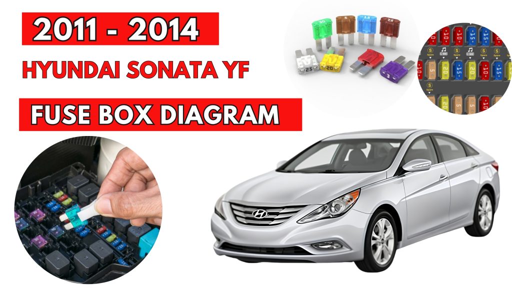
Hyundai Sonata YF (2011 – 2014) Fuse Box Location & Diagrams
The Hyundai Sonata YF (2011–2014) features multiple fuse boxes that protect important electrical systems and components. This blog explains the fuse box locations, detailed fuse diagrams, and fuse assignments, making it easier to identify the correct fuse for troubleshooting, maintenance, or replacing a blown fuse safely.
Fuse Box Location
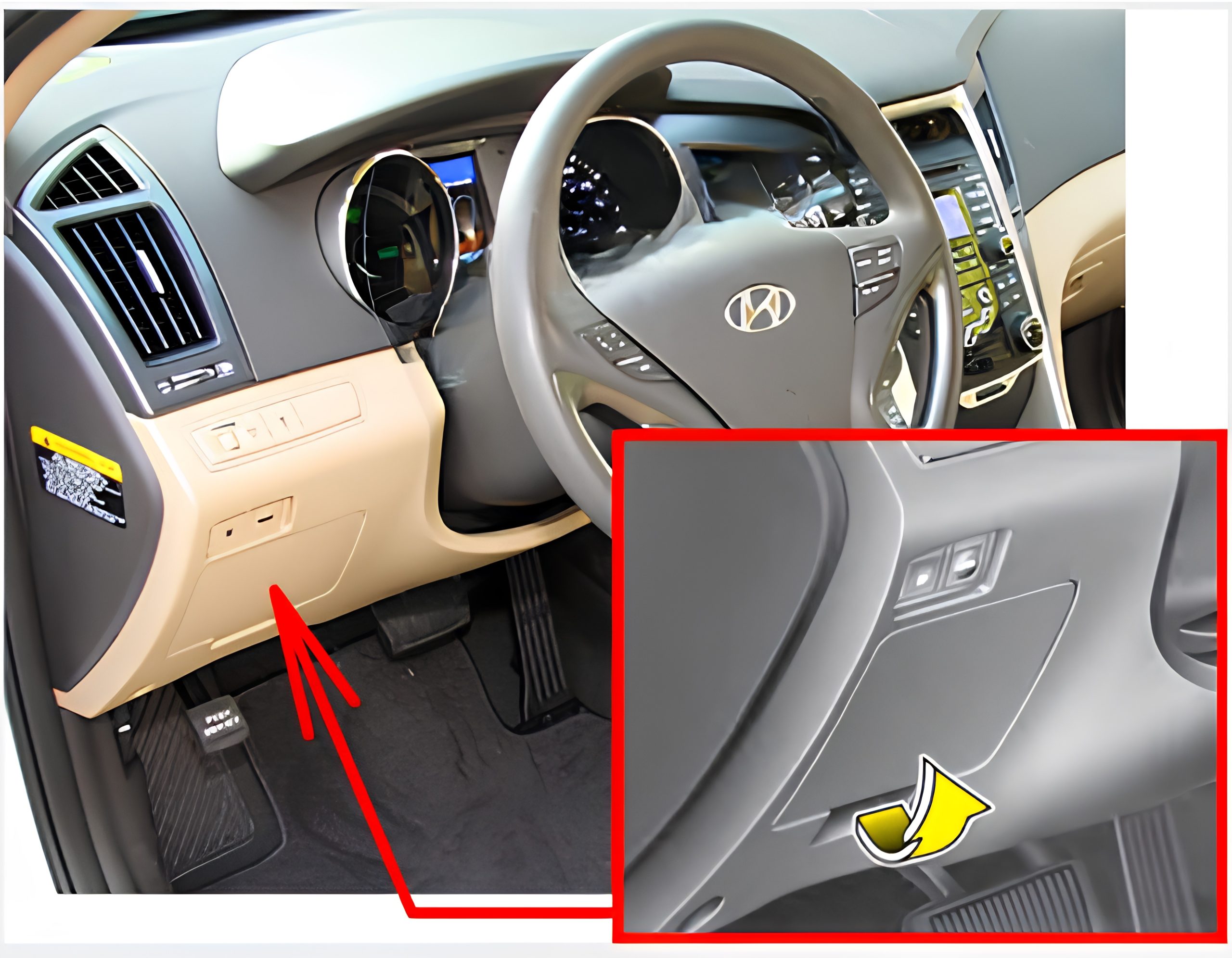
Passenger Compartment Fuse Box
The fuse box is located in the instrument panel (on the driver’s side), behind the cover.
Engine Compartment Fuse Box
The fuse box is located in the engine compartment (left side).
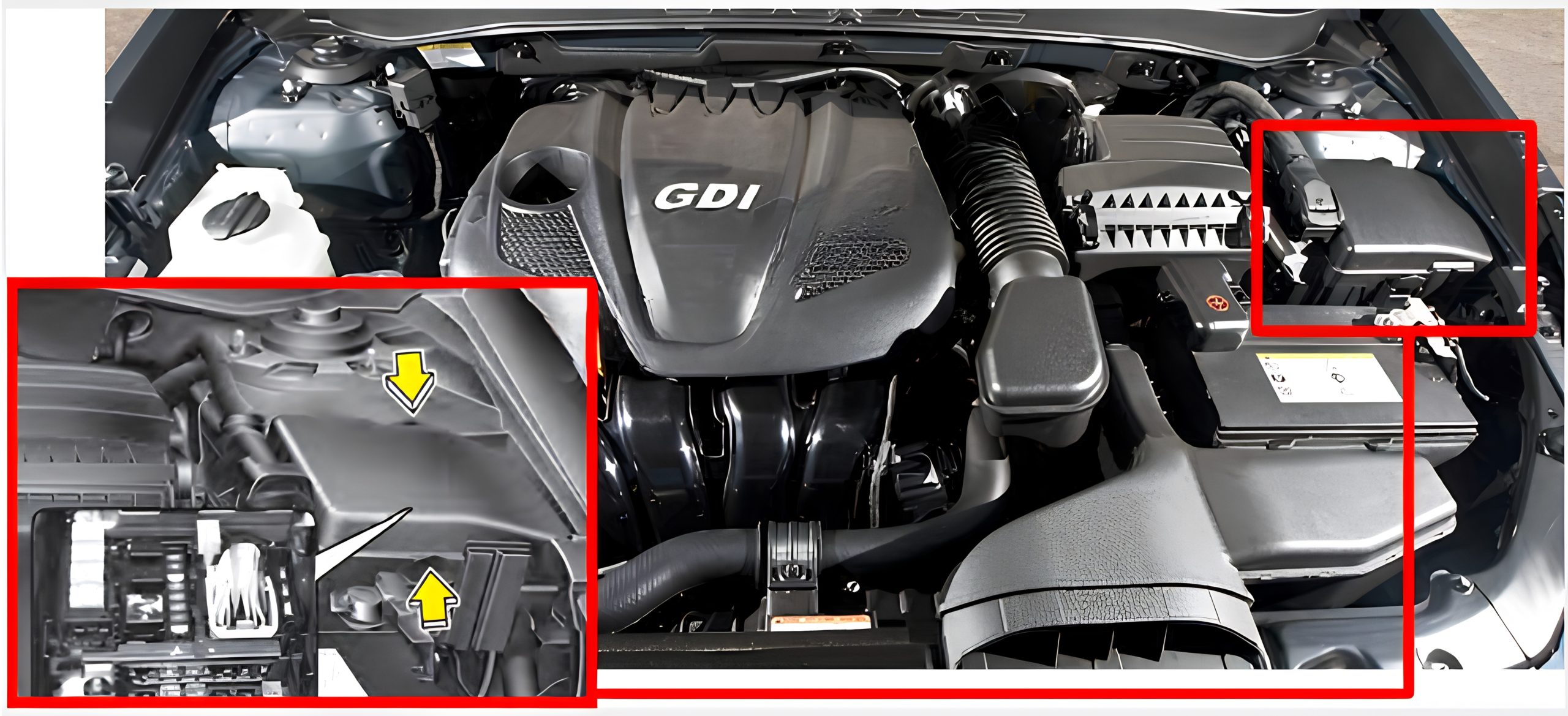
Fuse Box Diagrams
Passenger Compartment Fuse Box
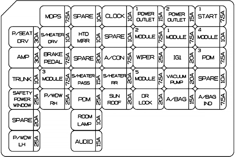
| Description | Amp rating | Protected component |
|---|---|---|
| P/SEAT DRI | 30A | Driver Manual Switch |
| AMP | 30A | AMR JBLAMP |
| TRUNK | 10A | Trunk Lid Relay, Trunk Room Lamp, Fuel Filler Door & Trunk Lid Switch |
| SAFETY POWER WINDOW | 25A | Safety Power Window Module |
| P/WDW ASST | 20A | Passenger Power Window Switch |
| P/WDW LH | 25A | Power Window Main Switch, Rear Power Window Switch LH |
| SPARE | 7.5A | – |
| SPARE | 10A | – |
| PDM2 | 7.5A | FOB Holder, Start Stop Button Switch. PDM, Smart Key Module |
| MODULE 3 | 7.5A | Key Solenoid, Sport Mode Switch |
| P/WDW RH | 25A | Power Window Main Switch, Rear Power Window Switch RH |
| SPARE | 10A | – |
| HTD MIRR | 10A | Driver/Passenger Power Outside Mirror |
| P/SEAT ASST | 20A | – |
| S/HEATER FRT | 15A | Driver/Passenger Seat Warmer Module |
| PDM | 25A | PDM |
| ROOM LP (POWER CONNECTOR) | 10A | Instrument Cluster, Driver/Passenger Door Lamp, Ignition Key ILL. & Door Warning Switch, BCM, Tire Pressure Monitoring Module, A/C Control Module, Room Lamp, Front Monitor, Glove Box Lamp, Data Link Connector, Vanity Lamp LH/RH, Auto Light & Photo Sensor, RF Receiver, Overhead Console Lamp, Clock |
| AUDIO (POWER CONNECTOR) | 15A | Audio, A/V & Navigation Head Unit |
| CLOCK | 10A | BCM, Clock, Front Monitor, Smart Key Module, PDM, Audio, Power Outside Mirror Switch, AMP, JBL AMP, Overhead Console Lamp, Rear Camera Module. A/V & Navigation Head Unit |
| SPARE | 10A | – |
| A/CON | 7.5A | E/R Fuse & Relay Box(Blower Relay), A/C Control Module |
| S/HEATER RR | 20A | Rear Seat Warmer Switch LH/RH |
| SUN ROOF | 20A | Sunroof Motor |
| POWER OUTLET 1 | 15A | Front Power Outlet #1 |
| MODULE 2 | 7.5A | BCM, Rear Camera Module, Electro Chromic Mirror, Sunroof Motor |
| WIPER | 25A | E/R Fuse & Relay Box(Wiper Relay), Front Wiper Motor, Multifunction Switch(Wiper) |
| MODULE 5 | 7.5A | PDM |
| DR LOCK | 20A | Door Lock/Unlock Relay |
| POWER OUTLET 2 | 15A | Front Power Outlet #2 |
| MODULE 1 | 7.5A | Instrument Cluster(ON/START Input), Clock, Sport Mode Switch IND., Audio, Driver/Passenger Seat Warmer Module, BCM |
| IG 1 | 20A | E/R Fuse & Relay Box (Fuse – ESC 3 10A, ECU 4 10A, B/UP LP 10A, TCU 2 10A) |
| SPARE | 20A | – |
| A/BAG | 15A | SRS Control Module, Telltale Lamp, Passenger Weight Classification Sensor |
| START 1 | 7.5A | W/O Smart Key-Ignition Lock Switch. Burglar Alarm Relay, E/R Fuse & Relay Box (Start 1 Relay) With Smart Key-PDM |
| MDPS | 10A | Yaw Rate Sensor, ESP Off Switch, EPS Control Module |
| PDM 3 | 7.5A | PDM, Smart Key Module |
| SPARE | 10A | – |
| A/BAG IND. | 7.5A | Instrument Cluster(IND-) |
| VACUUM PUMP | 20A | Vacuum pump |
Engine Compartment Fuse Box
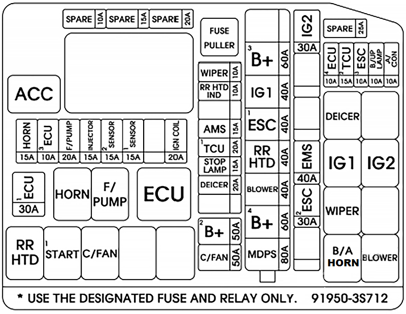
| Description | Amp rating | Protected component |
|---|---|---|
| MULTI FUSE: | ||
| C/FAN HI (2.0 TGDI) B+ 2 | 60A | C/Fan High Relay 2011: I/P Junction Box (Fuse – SUNROOF 20A, DR LCOK 20A, IPS 1 /IPS 4 /IPS 6 /IPS 7 /IPS9, Power Connector – ROOM LP 10A) |
| B+ 3 | 60A | I/P Junction Box (Fuse – P/WDW ASST 20A, P/WDW LH 25A, P/WDW RH 25A , TRUNK 10A, S/HEATER FRT 15A. PDM 25A, MODULE 3 7.5A. SAFETY POWER WINDOW 25A, Power Connector – AUDIO 15A, Power Window Relay) |
| IGN 1 | 40A | W/O Smart Key – Ignition Switch, With Smart Key – ACC Relay, IG1 Relay |
| ESC 1 | 40A | ESC Module, Multipurpose Check Connector |
| RR HTD | 40A | RR HTD Relay |
| BLOWER | 40A | Blower Relay |
| B+ 4 | 60A | I/P Junction Box (Fuse – P/SEAT DRIV 30A, AMP 30A, PDM 2 7.5A, IPS 2 /IPS 3 /IPS 5 /IPS 8) |
| MDPS | 80A | EPS Control Module |
| FUSE: | ||
| B+ 2 | 50A | I/P Junction Box (Fuse – SUNROOF 20A, DR LCOK 20A, IPS 1 /IPS 4 /IPS 6 /IPS 7 /IPS 9, Power Connector – ROOM LP 10A) |
| A/CON | 10A | A/C Control Module (Auto) |
| B/UP LP | 10A | Back-up Lamp Switch (M/T), B/UP LP Relay (A/T) |
| ESC 3 | 10A | ESC Module, Multipurpose Check Connector |
| TCU 2 | 15A | Vehicle Speed Sensor (M/T), Transaxle Range Switch (A/T), Start2 Relay |
| ECU 4 | 10A | Stop Lamp Switch, PCM |
| IGN 2 | 30A | W/O Smart Key – Ignition Switch, Startl Relay, With Smart Key – Start 1 Relay, IG 2 Relay |
| EMS | 40A | EMS Box (Fuse – HORN 15A, ECU 3 10A, ECU 1 30A, F/PUMP 20A) |
| ESC 2 | 30A | ESC Module, Multipurpose Check Connector |
| WIPER | 10A | PCM |
| RR HTD IND | 10A | A/C Control Module |
| AMS | 15A | Battery Sensor |
| TCU 1 | 20A | PCM |
| STOP LP | 15A | Stop Lamp Switch |
| DEICER | 20A | Deicer Relay |
| SPARE | 20A | – |
| C/FAN (2.4 GDI) | 40A | C/Fan Low Relay, C/Fan High Relay |
| C/FAN LO (2.0 TGDI) | 40A | C/Fan Low Relay |
| IGN COIL | 20A | Ignition Coil #1 /#2 /#3 /#4, Condenser |
| SENSOR 1 | 15A | Oxygen Sensor (Up), Oxygen Sensor (Down) |
| SENSOR 2 | 15A | Immobilizer Module, Camshaft Position Sensor #1 /#2, Purge Control Solenoid Valve. Variable Intake Solenoid Valve, Crankshaft Position Sensor, Oil Control Valve #1 /#2, Canister Close Valve |
| INJECTOR | 15A | F/Pump Relay |
| F/PUMP | 20A | F/Pump Relay |
| ECU 3 | 10A | PCM |
| HORN | 15A | Horn Relay, B/Horn Relay |
| ECU 1 | 30A | ECU Relay |
| SPARE | 25A | – |
| SPARE | 20A | – |
| SPARE | 15A | – |
| SPARE | 10A | – |
Related Posts: