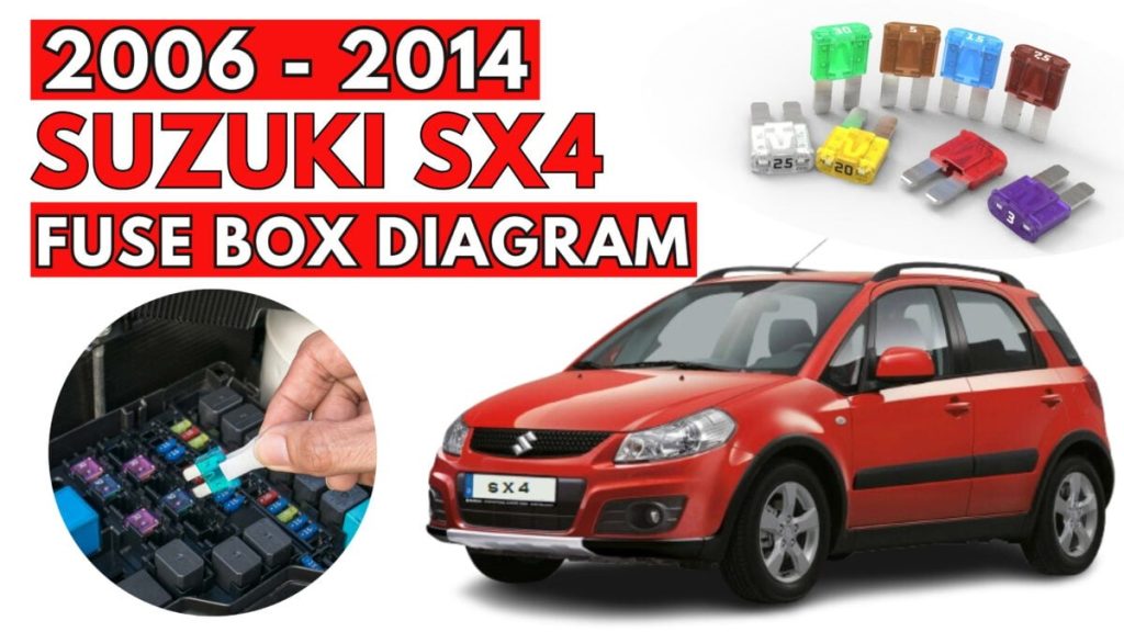
Suzuki SX4 (2006 – 2014) Fuse Box Diagrams & Location
Passenger Compartment Fuse Box
Suzuki SX4 (2006 to 2014)
Fuse Box Location
It is located under the instrument panel (on the driver’s side).
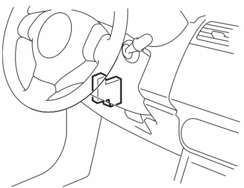
Fuse Box Diagram
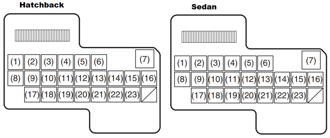
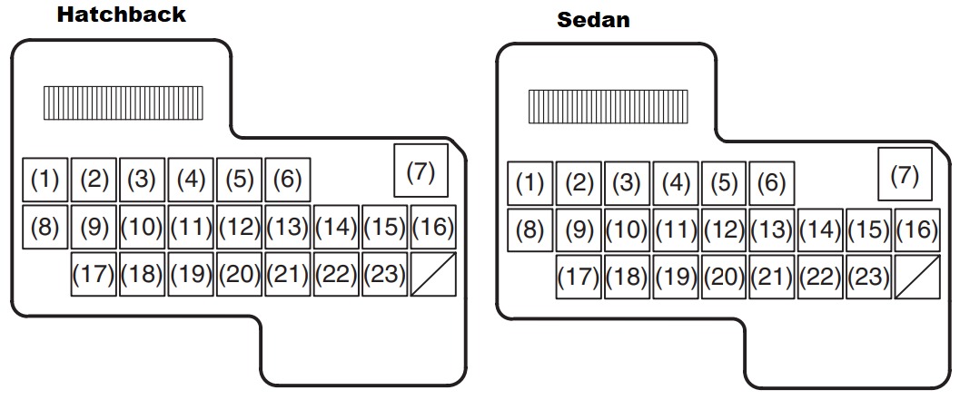
| № | Amp | Fused function |
|---|---|---|
| 1 | 15 | Rear wiper |
| 2 | 15 | Ignition coil |
| 3 | 10 | Back-up light |
| 4 | 10 | Meter |
| 5 | 15 | Accessory |
| 6 | 15 | Accessory 2 |
| 7 | 30 | Power window |
| 8 | 30 | Wiper |
| 9 | 10 | IG1 SIG |
| 10 | 15 | Air bag |
| 11 | 10 | Anti-lock brake system |
| 12 | 15 | Suzuki: 4WD Maruti: Tail light |
| 13 | 15 | Stop light |
| 14 | 20 | Door lock |
| 15 | 10 | ECU (Diesel only) |
| 16 | 10 | ST SIG |
| 17 | 15 | Seat heater |
| 18 | 10 | IG 2 SIG |
| 19 | 10 | Tail light |
| 20 | 15 | Dome |
| 21 | 30 | Rear defogger |
| 22 | 15 | Horn / Hazard |
| 23 | 15 | Audio |
| 24 | 30 | Rear defogger (Sedan) |
Engine Compartment Fuse Box
Suzuki SX4 (2006 to 2014)
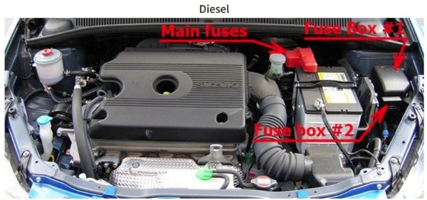
Fuse Box Location
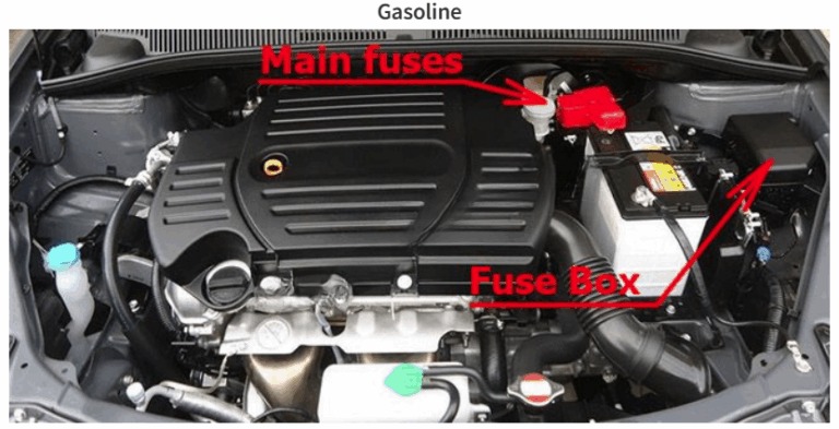
Fuse box diagram (Gasoline)
Assignment of the fuses and relays in the engine compartment (Gasoline)
| № | Amp | Fused function |
|---|---|---|
| 1 | 80 | All electric load |
| 2 | 50 | Power window, Ignition, Wiper, Starter |
| 3 | 50 | Tail light, Rear defogger, Door lock, Hazard/Horn, Dome |
| 4 | – | Not used |
| 5 | – | Not used |
| 6 | 15 | Head light (Right) |
| 7 | 15 | Head light (Left) |
| 8 | 20 | Front fog light |
| 9 | – | Not used |
| 10 | 40 | ABS control module |
| 11 | 30 | Radiator fan |
| 12 | 30 | ABS control module |
| 13 | 30 | Starting motor |
| 14 | 50 | Ignition switch |
| 15 | 30 | Blower fan |
| 16 | 20 | Air compressor |
| 17 | 15 | Throttle motor |
| 18 | 15 | Automatic transaxle |
| 19 | 15 | Fuel injection |
| Relays | ||
| 20 | Automatic transaxle relay | |
| 21 | Air compressor relay | |
| 22 | Fuel pump relay | |
| 23 | Condenser fan relay | |
| 24 | Front fog light relay | |
| 25 | Throttle motor relay | |
| 26 | FI MAIN | |
| 27 | Starting motor relay | |
| 28 | Radiator fan relay | |
| 29 | Radiator fan relay 2 | |
| 30 | Radiator fan relay 3 |
Fuse box diagram (Diesel)
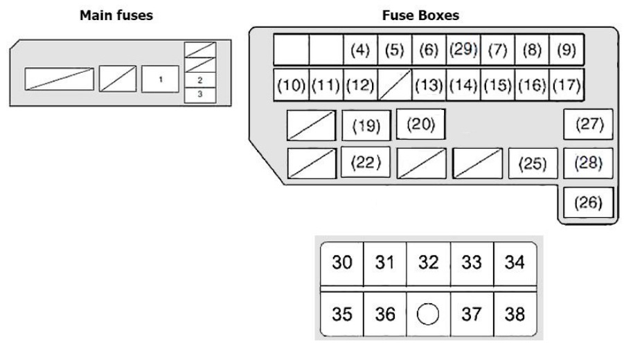
Assignment of the fuses and relays in the engine compartment (Diesel)
| No | Amp | Function/component |
|---|---|---|
| 2 | 20 | FI |
| 3 | 10 | INJ DVR |
| 4 | 15 | Head light (Right) |
| 5 | 15 | Head light (Left) |
| 6 | 20 | Front fog light |
| 7 | 60 | Power steering control module |
| 8 | 40 | ABS control module |
| 0 | 30 | Radiator fan |
| 10 | 30 | ABS control module |
| 11 | 30 | Starting motor |
| 12 | 50 | Ignition switch |
| 13 | 30 | Blower fan |
| 14 | 10 | Air compressor |
| 15 | 20 | Fuel, pump |
| 16 | 30 | CDSR |
| 17 | 30 | Fuel injection |
| 29 | 50 | IGN2 |
| 30 | 80 | Glow Plug |
| 31 | 30 | Fuel Heater |
| 32 | 140 | Main |
| 33 | 50 | Lamp |
| 34 | 30 | Sub Htr1 |
| 35 | 30 | Sub Htr 3 |
| 36 | 30 | Sub Htr 2 |
| 37 | – | +B2 |
| 38 | – | +B1 |
| Relays | ||
| 1 | FI Main relay | |
| 18 | Not used | |
| 19 | Air compressor relay | |
| 20 | Fuel pump relay | |
| 21 | Not used | |
| 22 | Front fog light relay | |
| 23 | Not used | |
| 24 | Not used | |
| 25 | Starting motor relay | |
| 26 | Radiator fan relay | |
| 27 | RDTR fan 3 relay | |
| 28 | RDTR fan 2 relay |