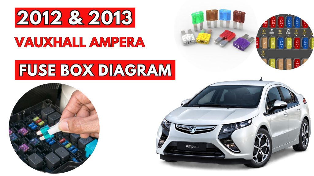
Vauxhall Ampera (2012 & 2013)Fuse Box Location & Diagrams
The Vauxhall Ampera (2012–2013) uses fuse boxes to protect important electrical circuits and components. Knowing the correct fuse locations and assignments makes troubleshooting electrical problems easier. This guide covers fuse box locations, diagrams, fuse ratings, and protected components for the Vauxhall Ampera.
Fuse Box Location
Passenger Compartment Fuse Box
Left Side
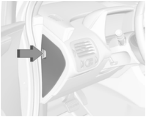
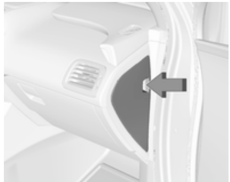
The left instrument panel fuse box is located on the left side end of the instrument panel. To access the fuses, open the fuse panel door by pulling out. A fuse puller is located in the engine compartment fuse box.
Right Side
The right instrument panel fuse box is located on the right side end of the instrument panel. To access the fuses, open the fuse panel door by pulling it out. A fuse puller is located in the engine compartment fuse block.
Engine Compartment Fuse Box
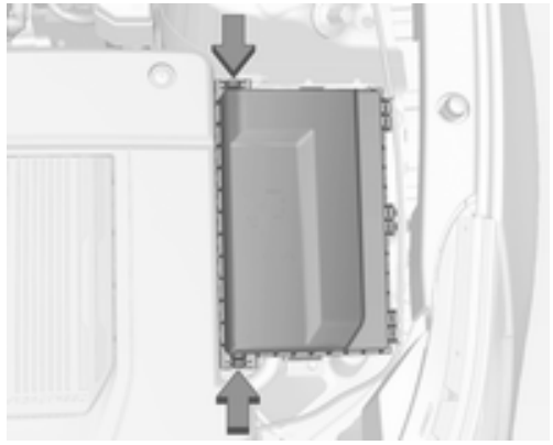
The fuse box is in the front left of the engine compartment. To open the fuse block cover, press the clips at the front and back and rotate the cover up to the side.
Load Compartment Fuse Box
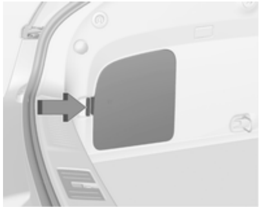
The fuse box is on the left side of the load compartment behind a cover. Remove the cover. A fuse puller is located in the engine compartment fuse box.
Fuse Box Diagrams
Passenger Compartment Fuse Box
Left Side
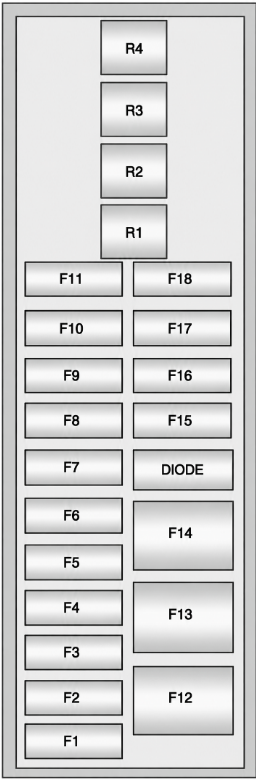
| Fuse No. | Usage |
|---|---|
| F1 | Power outlet – Top of IP storage bin |
| F2 | Radio |
| F3 | Instrument cluster (left hand drive) |
| F4 | Infotainment display |
| F5 | Heating, ventilation & air conditioning / Integrated centre stack switches |
| F6 | Airbag (Sensing diagnostic module) |
| F7 | Left primary data link connector (left hand drive), Left secondary data link connector (right hand drive) |
| F8 | Column lock (left hand drive) |
| F9 | Hands-free phone |
| F10 | Body control module 1 / Body control module electronics / Remote entry / Power moding / Centre high-mounted stoplight / Number plate lights / Left daytime running light / Left position lights / Tailgate release relay control / Washer pump relay control / Switch indicator lights |
| F11 | Body control module 4 / Left headlight |
| F12 | Blower (left hand drive) |
| F13 | – |
| F14 | – |
| F15 | Power outlet (Inside floor console / Rear of floor console) |
| F16 | – |
| F17 | – |
| F18 | – |
To reinstall the door, insert the bottom tab first, then push the door back into its original location.
Right Side
| Fuse No. | Usage |
|---|---|
| F1 | Steering wheel switch backlighting |
| F2 | Column lock (right hand drive) |
| F3 | Cluster (right hand drive) |
| F4 | Body control module 3 / Right headlight |
| F5 | Body control module 2 / Body control module electronics / Tail light / Right daytime running light / Shifter lock / Switch backlighting / Rear fog light |
| F6 | Body control module 5 / Retained accessory power relay control / Right front turn signal light / Left rear stop and turn signal light / Right position lights / Remote PRNDL |
| F7 | Body control module 6 / Map lights / Courtesy lights / Reversing lights |
| F8 | Body control module 7 / Left front turn signal / Right rear stop and turn signal light / Child security lock relay control |
| F9 | Body control module 8 / Locks |
| F10 | Right secondary data link connector (left hand drive), Right primary data link connector (right hand drive) |
| F11 | Intrusion and inclination sensor |
| F12 | Blower motor (left hand drive) |
| F13 | – |
| F14 | – |
| F15 | – |
| F16 | – |
| F17 | – |
| F18 | – |
To reinstall the door, insert the bottom tab first, then push the door back into its original location.
Engine Compartment Fuse Box
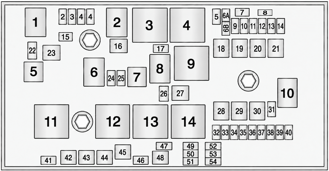
| Fuse No. | Fuse Type | Usage |
|---|---|---|
| 1 | Mini fuse | Engine control module – switched power |
| 2 | Mini fuse | Emissions |
| 3 | Mini fuse | – |
| 4 | Mini fuse | Ignition coils / Injectors |
| 5 | Mini fuse | Column lock |
| 6 | Mini fuse | – |
| 7 | Mini fuse | – |
| 8 | Mini fuse | – |
| 9 | Mini fuse | Heated mirrors |
| 10 | Mini fuse | Air conditioning control module |
| 11 | Mini fuse | Traction power inverter module – Battery |
| 12 | Mini fuse | – |
| 13 | Mini fuse | Cabin heater pump and valve |
| 14 | Mini fuse | Theft deterrent — Power sounder |
| 15 | Mini fuse | Traction power inverter module and transmission control module — Battery |
| 16 | J-case fuse | – |
| 17 | Mini fuse | Engine control module — Battery |
| 18 | J-case fuse | – |
| 19 | J-case fuse | Front power window |
| 20 | J-case fuse | – |
| 21 | J-case fuse | Antilock brake system electronic control unit |
| 22 | Mini fuse | Left high-beam headlight |
| 23 | J-case fuse | Charge port door |
| 24 | Mini fuse | – |
| 25 | Mini fuse | – |
| 26 | Mini fuse | Theft deterrent — Horn |
| 27 | J-case fuse | – |
| 28 | J-case fuse | – |
| 29 | J-case fuse | – |
| 30 | J-case fuse | Antilock brake system motor |
| 31 | Mini fuse | – |
| 32 | Mini fuse | Run/Crank — Sensing diagnostic module, instrument cluster, passenger airbag display, headlight level switch, automatic dimming inside rearview mirror |
| 33 | Mini fuse | Run/Crank — Vehicle integration control module |
| 34 | Mini fuse | Vehicle integration control module — Battery |
| 35 | Mini fuse | – |
| 36 | Mini fuse | Power electronics coolant pump |
| 37 | Mini fuse | Cabin heater control module |
| 38 | Mini fuse | Rechargeable energy storage system (high-voltage battery) coolant pump |
| 39 | Mini fuse | Rechargeable energy storage system (high-voltage battery) control module |
| 40 | Mini fuse | Front windscreen washer |
| 41 | Mini fuse | Right high-beam headlight |
| 42 | J-case fuse | Right cooling fan |
| 43 | J-case fuse | Front wipers |
| 44 | J-case fuse | Charger |
| 45 | J-case fuse | – |
| 46 | Mini fuse | – |
| 47 | Mini fuse | – |
| 48 | J-case fuse | Left cooling fan |
| 49 | Mini fuse | – |
| 50 | Mini fuse | Run/Crank — Rear view camera, accessory power module, tyre pressure monitor, headlight levelling motors |
| 51 | Mini fuse | Run/Crank for ABS / Rechargeable energy storage system (high-voltage battery) |
| 52 | Mini fuse | Engine control module / transmission control module — Run/Crank |
| 53 | Mini fuse | Traction power inverter module — Run/Crank |
| 54 | Mini fuse | Run/Crank — Fuel system control module, air conditioning control module, on-board charger |
Load Compartment Fuse Box
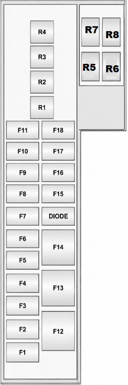
| Fuse No. | Usage |
|---|---|
| F1 | – |
| F2 | Fuel system control module |
| F3 | Passive start / Passive entry module |
| F4 | Heated seats |
| F5 | Driver door switches (Outside rearview mirror / Charge port door release / Refuel request / Driver window switch) |
| F6 | Fuel (Diurnal valve and evap. leak check module) |
| F7 | Accessory power module cooling fan |
| F8 | Amplifier |
| F9 | Digital audio broadcast |
| F10 | Regulated voltage control / Ultrasonic front and rear parking assist |
| F11 | Horn |
| F12 | Rear power windows |
| F13 | Electrical parking brake |
| F14 | Rear defog (Upper grid) |
| F15 | – |
| F16 | Tailgate release |
| F17 | – |
| F18 | – |