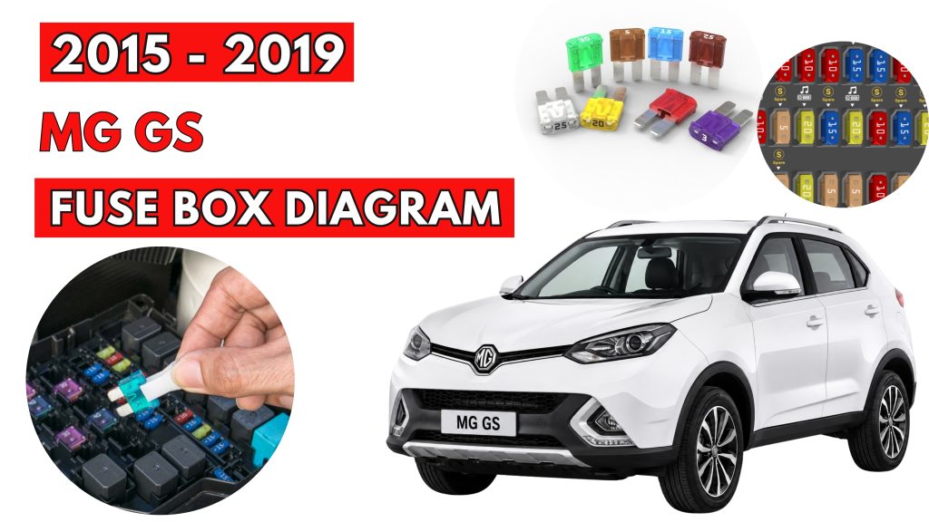
MG GS (2015 – 2019) Fuse Box Location & Diagrams
The MG GS (2015–2019) fuse box protects essential electrical systems throughout the vehicle. This blog provides clear fuse box locations and diagrams, helping you identify fuse positions, ratings, and protected components when checking or replacing fuses safely and efficiently.
Fuse Box Location
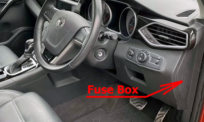
Passenger Compartment Fuse Box
Remove the driver-side dashboard panel cover to access the fuse box.
Engine Compartment Fuse Box
Press the lock catch to open the upper cover of the engine compartment fuse box.
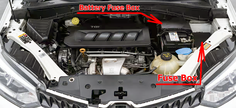
Fuse Box Diagrams
Passenger Compartment Fuse Box
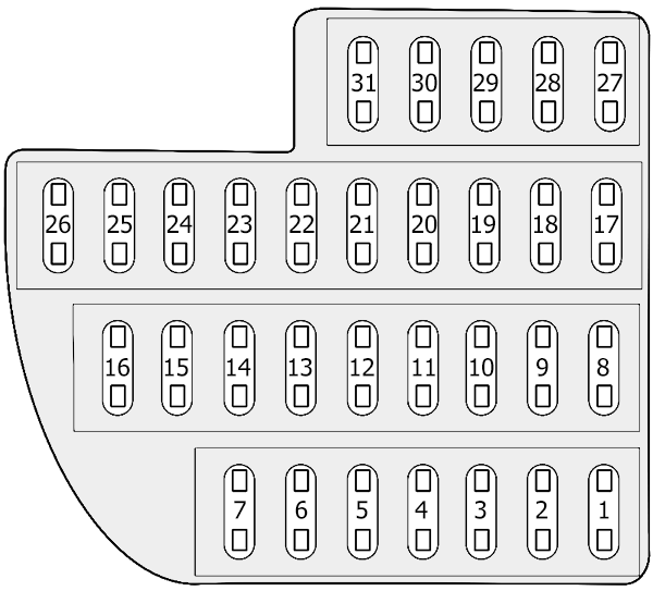
| № | Amps | Function |
|---|---|---|
| 1 | 15A | Rear accessories power socket |
| 2 | – | – |
| 3 | – | – |
| 4 | – | – |
| 5 | – | – |
| 6 | 5A | Radio |
| 7 | 15A | Front 12V power socket |
| 8 | 25A | TCM (7AT) |
| 9 | – | – |
| 10 | 5A | Driver door switch pack |
| 11 | 10A | Gateway |
| 12 | 5A | Parking distance control unit, rain sensor |
| 13 | 20A | Headlamp, dynamic headlamp levelling control module |
| 14 | 2A | Ignition switch |
| 15 | 5A | Immobiliser coil |
| 16 | 10A | Diagnostic socket |
| 17 | 5A | Slip control system |
| 18 | 5A | Power management DC convertor |
| 19 | 20A | Seat heater switch |
| 20 | – | – |
| 21 | 7.5A | PRND display, EPB Switch, exterior mirror adjustment, switch-stop/start system |
| 22 | 10A | Supplemental restraint system |
| 23 | – | – |
| 24 | – | – |
| 25 | 5A | Master light switch |
| 26 | – | – |
| 27 | – | – |
| 28 | 5A | Instrument pack |
| 29 | 10A | ATC controller / MTC controller |
| 30 | 5A | A/C and ICE interface |
| 31 | 15A | Radio/color radio/ NAV |
Engine Compartment Fuse Box
Fuse Box
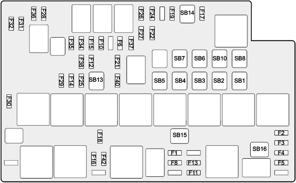
| № | Amps | Function |
|---|---|---|
| F1 | 10A | Engine control module |
| F2 | 15A | Engine control module |
| F3 | 20A | Upstream oxygen sensor, downstream oxygen sensor, clutch bottom sensor, variable camshaft timing exhaust, variable camshaft timing intake, electronic thermostat |
| F4 | 15A | Heat air flow meter, ignition coil 1~4 |
| F5 | 10A | Canister purge valve, wastegate control valve, dump valve, brake lamp switch sensor, oil control valve, neutral switch |
| F6 | 7.5A | Exterior mirror heater |
| F7 | – | – |
| F8 | 20A | Fuel pump relay |
| F9 | – | – |
| F10 | 30A | Driver door window lift motor |
| F11 | 5A | Supplemental restraint system |
| F12 | 25A | Body control module |
| F13 | 20A | Passenger power seat adjustment switch |
| F14 | 25A | Body control module |
| F15 | 30A | Front passenger door window lift switch |
| F16 | 10A | TCM (TST), engine control module, shift control module (TST) |
| F17 | 10A | Air conditioning compressor relay |
| F18 | 5A | Engine control module |
| F19 | 20A | Driver power seat adjustment switch |
| F20 | — | — |
| F21 | 10A | Ignition switch relay |
| F22 | 25A | Body control module |
| F23 | – | – |
| F24 | 5A | Transmission relay coil (TST) |
| F25 | 25A | Body control module |
| F26 | 30A | Rear left window lift switch |
| F27 | 30A | Rear right window lift switch |
| F28 | 20A | Horn relay |
| F29 | 25A | Front wiper relay |
| F30 | 20A | Front windscreen washer relay |
| F31 | 20A | Rear windscreen wiper relay |
| F32 | 20A | Rear windscreen washer relay |
| F33 | – | – |
| F34 | 10A | Front left headlamp |
| F35 | 10A | Front right headlamp |
| F36 | 30A | Headlamp washer relay |
| F37 | 15A | Front fog lamp relay |
| F38 | 25A | Body control module |
| F39 | – | – |
| F40 | 30A | Rear windscreen heater relay |
| F41 | – | – |
| F42 | 10A | Reverse lamp switch (6MT), body control module, instrument pack, MTC controller |
| SB1 | 30A | Main relay |
| SB2 | 60A | Cooling fan-high speed |
| SB3 | 50A | Cooling fan-middle speed |
| SB4 | 40A | KL.R power control relay |
| SB5 | 40A | Starter relay |
| SB6 | 30A | Slip control system-valve |
| SB7 | 40A | Slip control system-pump |
| SB8 | 40A | Blower relay |
| SB9 | – | – |
| SB10 | 25A | Body control module |
| SB11 | – | – |
| SB12 | – | – |
| SB13 | 40A | TCM (TST) |
| SB14 | 40A | Electrical park brake control module |
| SB15 | 40A | Power management DC convertor |
| SB16 | 40A | Cooling fan-low speed |
Battery Fuse Box
Press the lock catch (arrowed), remove the upper cover of the battery fuse box.
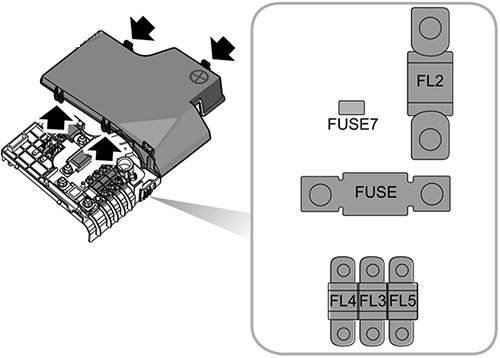
| Code | Amps | Function |
|---|---|---|
| FUSE | – | – |
| FUSE7 | 5A | Power management DC convertor |
| FL2 | 200A | Alternator |
| FL3 | 60A | Electronic power assisted steering |
| FL4 | 200A | Engine compartment fuse box |
| FL5 | 50A | Passenger compartment fuse box |
Related Posts: