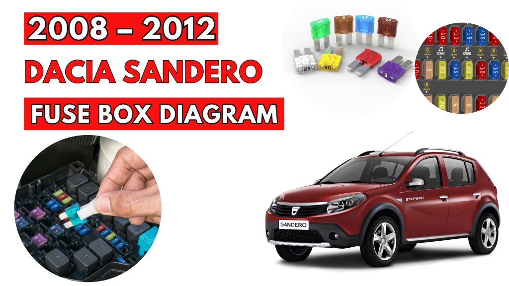
Dacia Sandero (2008–2012) Fuse Box Location & Diagrams
The Dacia Sandero (2008–2012) uses fuse boxes to protect important electrical circuits and components. Knowing the correct fuse locations and assignments makes troubleshooting electrical problems easier. This guide covers fuse box locations, diagrams, fuse ratings, and protected components for the Dacia Sandero.
Fuse Box Location
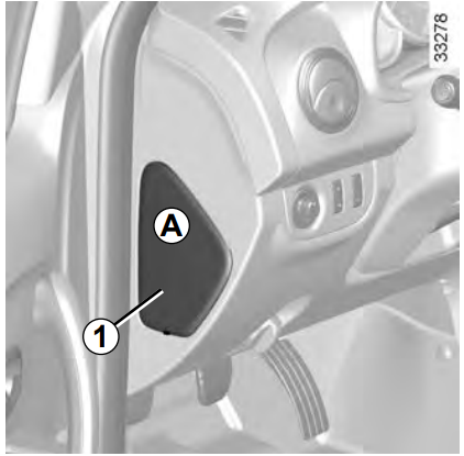
Passenger Compartment Fuse Box
If any electrical component does not work, check the condition of the fuses. Unclip flap A using notch 1 to help you.
Engine Compartment Fuse Box
Fuses in engine compartment B Some functions are protected by fuses located in the engine compartment (unit B).
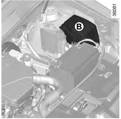
Special features of LPG versions The specific LPG 2 circuit shut-off fuseis located in the box B.
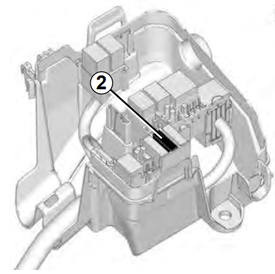
Fuse Box Diagrams
Passenger Compartment Fuse Box
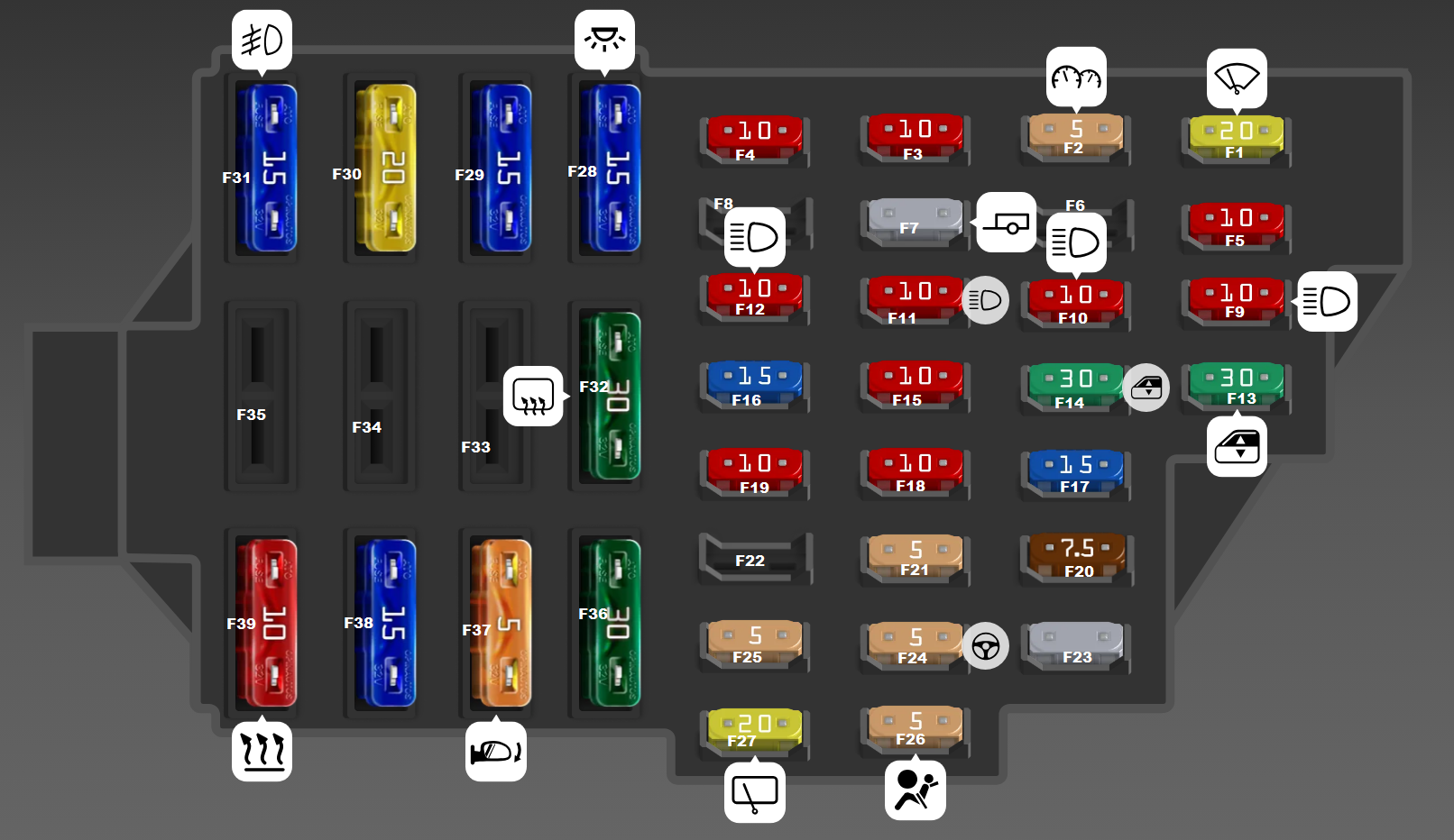
| Fuse No. | Fuse Type | Description |
|---|---|---|
| F1 | MINI 20A | Windshield wiper |
| F2 | MINI 5A | Instrument cluster, ECU |
| F3 | MINI 10A | Brake light switch, reversing light switch |
| F4 | MINI 10A | Electronic engine start blocking, airbag and seat belt pretensioner control unit |
| F5 | MINI 10A | Automatic transmission |
| F7 | MINI | Trailer |
| F9 | MINI 10A | Left headlight (low beam) |
| F10 | MINI 10A | Right headlight (low beam) |
| F11 | MINI 10A | Left headlight (high beam) |
| F12 | MINI 10A | Right headlight (high beam) |
| F13 | MINI 30A | Rear power windows |
| F14 | MINI 30A | Front power windows |
| F15 | MINI 10A | ABS control unit |
| F16 | MINI 15A | Heated front seats |
| F17 | MINI 15A | Sound horn |
| F18 | MINI 10A | Left side light, alarm switch, cigarette lighter |
| F19 | MINI 10A | Right side light |
| F20 | MINI 7.5A | Rear fog lamp switch |
| F21 | MINI 5A | Heated exterior mirrors |
| F23 | MINI | Security alarm installation position |
| F24 | MINI 5A | Power steering |
| F25 | MINI 5A | Gas equipment |
| F26 | MINI 5A | Airbag and seat belt pretensioner control unit |
| F27 | MINI 20A | Rear wiper, reversing light switch |
| F28 | ATO 15A | Interior lighting |
| F29 | ATO 15A | General power supply |
| F30 | ATO 20A | Body element locking system |
| F31 | ATO 15A | Fog lights |
| F32 | ATO 30A | Heated rear window |
| F36 | ATO 30A | Heating, air conditioning and interior ventilation fan |
| F37 | ATO 5A | Electric door mirrors |
| F38 | ATO 15A | Car radio |
| F39 | ATO 10A | Heating, air conditioning and ventilation systems |
| F1R | Relay | Burglar alarm, exterior light switch, daytime running light relay |
| F2R | Relay | Ambient light switch, passenger compartment fuse mounting block |
| F1R | Relay | Relay board power supply |
| F3R | Relay | Injection system relay power supply circuit, engine management electronic unit |
Engine Compartment Fuse Box
(Type 1)
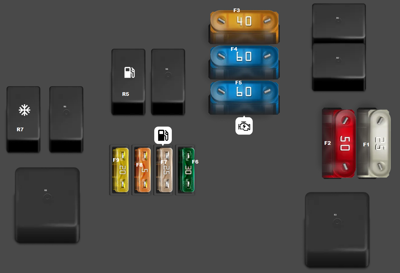
| Fuse No. | Fuse Type | Description |
|---|---|---|
| F1 | MAXI 25A | Anti-lock braking system (ABS) electrical control unit |
| F2 | MAXI 50A | Anti-lock braking system (ABS) electrical control unit |
| F3 | MAXI 40A | Power supply for engine cooling fan high-speed relay, relay plate, engine cooling fan relay, air conditioning compressor control relay |
| F4 | MAXI 60A | Multi-function switch, passenger compartment fuse box |
| F5 | MAXI 60A | Ignition switch, multi-function switch, daytime running lights relay, passenger compartment fuse box |
| F6 | ATO 30A | Relay plate power supply |
| F7 | ATO 25A | Fuel pump relay, injection lockout relay |
| F8 | ATO 5A | Injection electrical control unit, injection lockout relay |
| F9 | ATO 20A | Automatic gearbox central electrical unit (K4M engine only) |
| R1 | Relay | Front fog lights |
| R2 | Relay | Horn relay |
| R3 | Relay | Cold air blower system device relay |
| R4 | Relay | Injection lockout relay |
| R5 | Relay | Fuel pump relay |
| R6 | Relay | Engine cooling fan low-speed relay |
| R7 | Relay | Air conditioning clutch relay |
| R8 | Relay | Engine cooling fan high-speed relay |
(Type 2)
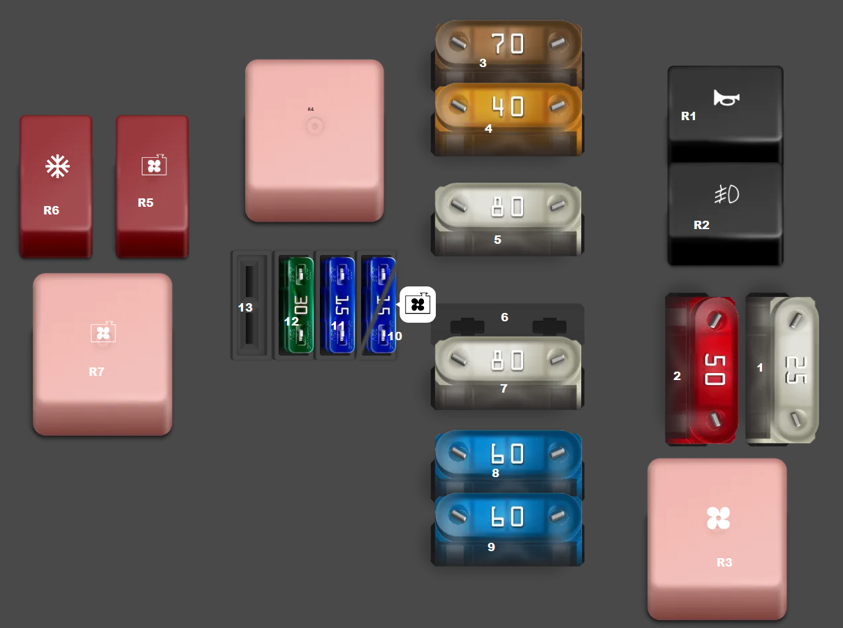
| Fuse No. | Fuse Type | Description |
|---|---|---|
| 1 | MAXI 25A | ABS control unit |
| 2 | MAXI 50A | ABS control unit |
| 3 | MAXI 70A | Glow plug control unit |
| 4 | MAXI 40A | A/C compressor relay, cooling fan high-speed relay, cooling fan low-speed relay |
| 5 | MAXI 80A | Power steering pump |
| 7 | MAXI 80A | Additional heater relay 1, additional heater relay 2 |
| 8 | MAXI 60A | Passenger compartment fuse box |
| 9 | MAXI 60A | Ignition switch, daytime running light system active |
| 10 | ATO 15A | Cooling fan, low-speed relay (30A is also used) |
| 11 | ATO 15A | Mass air flow sensor, fuel-in-water sensor |
| 12 | ATO 30A | Injection control unit |
| R1 | Relay | Horn relay |
| R2 | Relay | Front fog light relay |
| R3 | Relay | A/C blower motor |
| R4 | Relay | Diesel injection control unit relay |
| R5 | Relay | Cooling fan low-speed relay |
| R6 | Relay | A/C compressor clutch relay |
| R7 | Relay | Cooling fan high-speed relay |
RELATED POSTS: