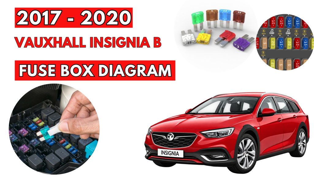
Vauxhall Insignia B (2017-2020) Fuse Box Location & Diagrams
The Vauxhall Insignia B (2017–2020) uses fuse boxes to protect important electrical circuits and components. Knowing the correct fuse locations and assignments makes troubleshooting electrical problems easier. This guide covers fuse box locations, diagrams, fuse ratings, and protected components for the Vauxhall Insignia B.
Fuse Box Location
Passenger Compartment Fuse Box
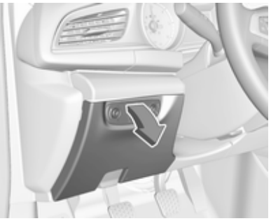
In left-hand drive vehicles, the fuse box is behind a cover in the instrument panel. Disengage cover at the side and remove.
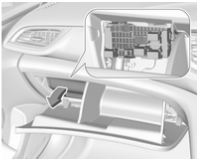
In right-hand drive vehicles, the fuse box is located behind a cover in the glovebox. Open the glovebox and remove the cover.
Engine Compartment Fuse Box
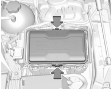
The fuse box is in the front left of the engine compartment. Disengage the cover and remove it.
Fuse Box Diagrams
Passenger Compartment Fuse Box
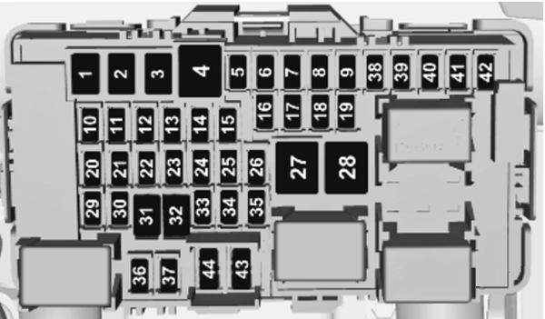
| № | Circuit |
|---|---|
| 1 | Left power window |
| 2 | Right power window |
| 3 | Body control module |
| 4 | Climate control fan |
| 5 | Body control module |
| 6 | Trailer provisions |
| 7 | Rear seat power folding |
| 8 | Body control module |
| 9 | Engine control module |
| 10 | Head-up display |
| 11 | NOx reduction/Pipe heater |
| 12 | NOx reduction/Soot sensor |
| 13 | UREA module |
| 14 | Heated steering wheel |
| 15 | Transmission control module |
| 16 | Amplifier |
| 17 | Alarm |
| 18 | Body control module |
| 19 | 2018: UREA module 2019-2020: AdBlue module |
| 20 | Body control module |
| 21 | Body control module |
| 22 | Body control module |
| 23 | Electric steering wheel lock |
| 24 | Airbag |
| 25 | Diagnostic connector |
| 26 | Power outlet load compartment |
| 27 | EBCM valve |
| 28 | Police provision |
| 29 | – |
| 30 | – |
| 31 | Steering wheel controls |
| 32 | Ignition switch |
| 33 | Climate control |
| 34 | Central gateway module |
| 35 | AUX/USB connector |
| 36 | Wireless charger |
| 37 | Rear wiper |
| 38 | Onstar |
| 39 | Display |
| 40 | Parking assist |
| 41 | Overhead console |
| 42 | Radio/Infotainment System |
Engine Compartment Fuse Box
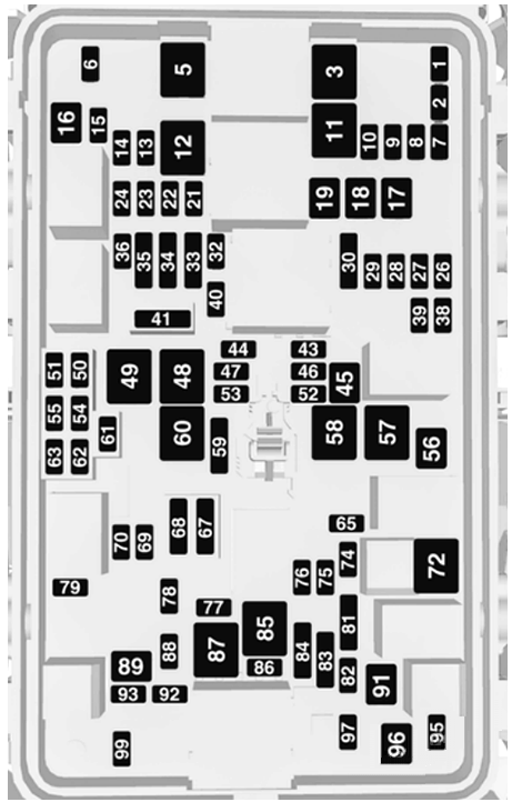
| № | Circuit |
|---|---|
| 1 | – |
| 2 | – |
| 3 | ABS |
| 4 | – |
| 5 | – |
| 6 | Tailgate |
| 7 | Fog light |
| 8 | Memory module |
| 9 | Heated windscreen |
| 10 | Seat lumbar |
| 11 | DC/DC battery |
| 12 | Heated rear window |
| 13 | Heated mirror |
| 14 | – |
| 15 | – |
| 16 | Front wiper |
| 17 | Power seat, passenger |
| 18 | Sunblind |
| 19 | Power seat, driver |
| 20 | – |
| 21 | Sunroof |
| 22 | Rear wiper/Airbag |
| 23 | Adaptive forward lighting |
| 24 | – |
| 25 | – |
| 26 | Transmission control module |
| 27 | Ignition/lnstrument panel |
| 28 | – |
| 29 | Rear view camera/Air vent |
| 30 | Malfunction indicator light/ Trailer |
| 31 | – |
| 32 | Camera |
| 33 | Seat heat front |
| 34 | Seat heat rear |
| 35 | Damping/AII-wheel drive |
| 36 | Fuel system |
| 37 | – |
| 38 | – |
| 39 | – |
| 40 | Steering wheel lock |
| 41 | – |
| 42 | – |
| 43 | Heated steering wheel |
| 44 | Headlight range adjustment |
| 45 | – |
| 46 | Engine control module |
| 47 | – |
| 48 | DC/DC converter/Air vent/EBoost |
| 49 | Rear door control module |
| 50 | – |
| 51 | – |
| 52 | – |
| 53 | – |
| 54 | – |
| 55 | – |
| 56 | Starter |
| 57 | – |
| 58 | – |
| 59 | Left headlight (LED) |
| 60 | Cooling fan |
| 61 | – |
| 62 | – |
| 63 | – |
| 64 | – |
| 65 | Climate control |
| 66 | – |
| 67 | – |
| 68 | – |
| 69 | Right high beam (Halogen)/ Right headlight (LED) |
| 70 | Left high beam (Halogen) |
| 71 | – |
| 72 | Starter |
| 73 | – |
| 74 | Transmission control module |
| 75 | Engine control module |
| 76 | Exhaust reduction system |
| 77 | – |
| 78 | Horn |
| 79 | Washer system |
| 80 | – |
| 81 | Engine control module |
| 82 | – |
| 83 | Ignition coil |
| 84 | Ignition coil |
| 85 | Powertrain |
| 86 | – |
| 87 | Diesel fuel heating |
| 88 | Air shutter |
| 89 | – |
| 90 | – |
| 91 | – |
| 92 | After boil pump |
| 93 | Electronic key system |
| 94 | – |
| 95 | Coolant pump |
| 96 | Diesel fuel heating |
| 97 | – |
| 98 | – |
| 99 | Coolant pump |